
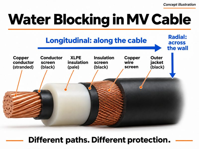
Water blocking in MV cable addresses two different paths: longitudinal protection limits water travelling along the cable, while radial protection restricts moisture entering across the cable wall. Water-swellable components and a continuous radial barrier therefore serve different purposes. A wet-route specification should identify the protected layers, the barrier construction and the verification method, together with the joints and cable-end seals that complete the system.

Start with the point where water meets the cable
A flooded duct surrounds the jacket with water. A damaged sheath creates a local entry point. An unsealed end exposes several cable layers at once. These conditions can occur on the same route, but they lead to different protection questions.
Consider an illustrative feeder pulled through a persistently wet duct. A sound outer sheath provides the first environmental protection. If that sheath is damaged, longitudinal blocking can help limit the distance water travels within the protected region. A radial barrier addresses the separate movement of moisture through the cable wall. The ends and accessories need protection that remains effective during storage, installation and service.
For XWA, the useful design question is: which path needs to be controlled, and in which cable layer? That question produces a clearer construction than a general request for a “waterproof cable”.
Following the cable length: define the blocked region
Longitudinal protection uses water-blocking components within selected cable regions. Water-swellable tapes, yarns or other designed blocking systems can restrict water movement along spaces in the assembly. Their position matters: blocking around the metallic screen and blocking within a conductor address different routes.
The screen region contains interfaces and spaces between components. A blocking system there needs to suit that arrangement and the insulation-screen interface. Where conductor water blocking is specified, the conductor construction needs its own provision. A water-blocking claim should make that distinction visible in the cable description.
Liquid-water penetration and water-vapour diffusion also describe different mechanisms. Published experimental work on axial ingress in MV XLPE cable shows why a local water exposure cannot be reduced to one universal travel distance. The construction and exposure conditions matter. We would retain those conditions with the test result rather than turn a laboratory observation into a lifetime guarantee.
Crossing the cable wall: continuity becomes decisive
A radial moisture barrier can use a continuous metallic system, such as a suitably bonded or welded metallic layer, according to the cable design. Its function depends on the complete barrier: material, seam or overlap arrangement, bonding and continuity through the cable length.
Copper screen wires perform an electrical duty and leave spaces between the wires. A continuous moisture barrier performs a different duty. Both may be present in the same cable, and the specification should keep their functions separate.
The same distinction applies to the outer polymer jacket. A PE sheath is an important environmental component, while an additional radial barrier provides a further moisture-control feature. Longitudinal blocking and radial protection can be combined where the installation requires both.
In the XWA range, N2XS(F)2Y cable addresses the longitudinally water-blocked construction, while N2XS(FL)2Y cable adds the specified radial moisture-barrier arrangement. Select the voltage rating, conductor area and metallic-screen duty alongside those features.
Match the verification to the protection being claimed
IEC 60502-2 includes longitudinal water-penetration provisions for the covered MV cable constructions and recommends considering radial water-ingress risk when determining applications. The selected test and acceptance criteria need to match the actual blocking claim.
| Protection question | Relevant evidence | What to connect to the project |
|---|---|---|
| Does water travel along the specified region? | Applicable longitudinal water-penetration test | Tested layer, specimen arrangement, exposure conditions and acceptance criteria |
| How is radial moisture entry controlled? | Barrier material, continuity and seam/overlap construction; agreed qualification evidence | The barrier design, manufacturing controls and accessory interfaces |
| Has the protective oversheath remained sound? | Applicable oversheath inspection or testing | Handling history, installation stage and relevant cable specification |
| Are open ends and accessories protected? | End-seal condition and accessory installation records | Storage, pulling, joint preparation and completed circuit |
For the protective-covering test context, see the IEC oversheath testing framework. Oversheath checks, longitudinal water-penetration tests and main-insulation electrical tests answer different questions. Together, appropriately selected checks give a more useful picture of cable-system condition than one result treated as proof of every protective function.
Keep protection continuous through delivery and installation
The factory cable design is one part of the water-protection system. Cable ends are exposed when lengths are cut and prepared. Storage caps, resealing after cutting and the preparation sequence help preserve the intended protection before the final joint or termination is complete.
At an accessory, the metallic screen, radial barrier and outer sheath each meet a defined interface. The accessory instructions and approved cable drawing should agree on those interfaces. A change in barrier construction can affect preparation and sealing details even when the nominal conductor area stays the same.
Our engineering preference is to resolve the accessory fit before cable lengths are released for the project. It is easier to coordinate one cable-and-accessory construction than to discover a barrier detail at the joint bay after delivery.
The related MV underground route guide places those interfaces within the wider duct, soil and installation environment.
A precise water-blocking requirement is short but complete
A practical project description can follow this form: MV XLPE cable, specified voltage and conductor/screen sizes, longitudinal blocking in the stated cable region, radial barrier where required, compatible joint and termination system, and agreed water-penetration and oversheath verification.
That description keeps the electrical duty, water paths and interfaces together without burying the requirement in a long list of general claims. It also gives XWA a useful basis for discussing the construction and quotation.
For a wet-route cable enquiry, send the cable schedule, route exposure, required lengths and accessory information to info@xwacable.com. Identify whether the route involves occasional flooding, persistent groundwater or another defined exposure so the discussion starts with the right protection concept.