
XWA Power & Cable | Submarine Cable
Inter array cable connects offshore wind turbines to one another and to the offshore substation, collecting generated power within the wind farm. It combines subsea electrical insulation, water protection and mechanical armour for the collection network.
Array network classes: 33 kV and 66 kV AC.
XWA welcomes inter-array cable enquiries for offshore wind projects. Three-core power construction, integrated optical communication and route-specific protection form the basis of the project discussion.
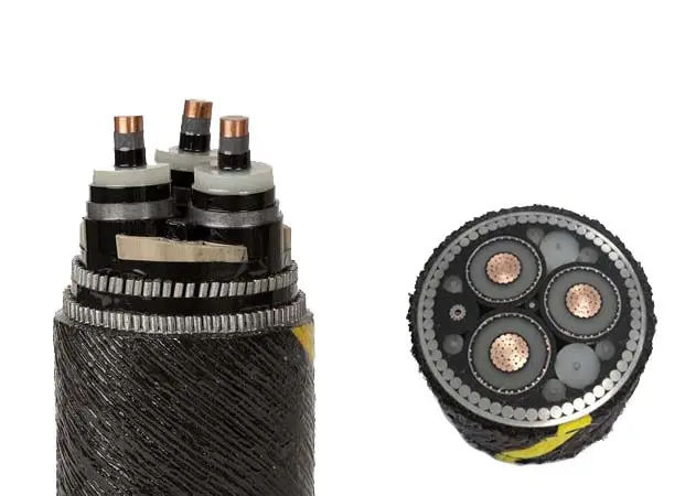
Array cables collect power inside the wind farm
In a typical offshore collection network, successive turbine connections form strings that carry power towards the offshore substation. Cable sections closer to the collection point can carry the output of more turbines. This makes the electrical position of each section important when defining conductor area and thermal duty.
An export cable serves a different route: it transfers the collected power from the offshore substation towards shore. Keeping these functions distinct helps align the cable construction with the network voltage, route length and installation arrangement.

Three power cores, water protection and marine armour
A three-core armoured arrangement brings the phase conductors together in one subsea assembly. An integrated optical unit can provide a communication path, while water-blocking measures and the outer protective system address the submerged route. The layer design is selected as a complete system rather than by adding armour to a land cable.
| Component | Function in the selected design |
|---|---|
| Copper conductor | Carries the collection-circuit current; area follows electrical and thermal assessment. |
| Conductor screen, insulation and insulation screen | Control the electric field around each insulated power core. |
| Metallic screen / sheath | Provides the specified electrical screen and fault-current path. |
| Water protection | Longitudinal blocking and a radial barrier or qualified wet-design approach, as specified. |
| Optical unit | Communication and project-specified sensing interfaces where included. |
| Core assembly, bedding and armour | Support the three-core arrangement and the installation mechanical duty. |
| Outer protection | Protects the armour system for the defined marine environment. |
We would give the sheath, water protection and accessories equal attention to conductor size. A well-matched power core still needs compatible joints, terminations and turbine entries to become a reliable installed connection.
33 kV and 66 kV inter array cable specifications
33 kV and 66 kV are familiar collection-network voltage classes. The complete cable designation also states the conductor-to-earth voltage and maximum system voltage. These values depend on the network and insulation coordination; a network class alone is not the full cable rating.
| Specification field | Project definition |
|---|---|
| Collection network | 33 kV or 66 kV AC; complete U0/U(Um) rating agreed for the system. |
| Power-core arrangement | Three-core reference configuration; conductor area set per circuit section. |
| Insulation system | Extruded XLPE or EPR design with corresponding screens and qualification. |
| Optical configuration | Fibre count and optical-unit protection to the communication specification. |
| Thermal calculation | Route-specific burial, seabed thermal conditions, grouping and operating load. |
| Mechanical data | Installation tension, bend limits, armour design and submerged weight. |
| Interfaces | Turbine entries, hang-offs, terminations and any offshore joints. |
Higher voltage changes more than cable ampacity
At the same three-phase active power and power factor, doubling voltage halves the ideal load current. That is a useful reason to evaluate 66 kV collection, but it is not an automatic instruction to halve conductor area: losses, soil conditions, charging current, fault duty and installation loads remain part of the assessment. Switchgear and terminations must also suit the chosen voltage.
For a multi-section turbine string, a single conductor size is not always the most useful starting assumption. Comparing the loading of each section can identify where thermal margin is needed and where additional copper would deliver little benefit.
Seabed routes and turbine entries shape the cable design
A fixed-bottom wind farm combines a static seabed route with mechanically demanding entry and installation zones. Pull-in operations, vessel handling, seabed contact and burial protection affect the armour and bend requirements. Burial depth is assessed against route risk and thermal performance rather than selected as a universal number.
For floating wind, the connection can experience repeated motion, tension variation and fatigue. A dynamic section therefore needs its own design assessment and compatible accessories. Static seabed sections are assessed for their installed route and handling loads; dynamic sections additionally address repeated movement, fatigue life and the associated accessories.
We favour discussing the route and installation method early. A heavier armour layer can improve one mechanical margin while changing submerged weight, handling and bending behaviour. That trade-off is easier to resolve before the cable and accessory interfaces are fixed.
Testing and delivery built around the cable system
The inspection and test plan brings together conductor checks, dimensional inspection, applicable electrical routine tests, material assessment and project-specified mechanical qualification. Factory tests, installation checks and system acceptance each address a different stage of the cable’s service path.
DNV-ST-0359 addresses subsea cable systems for wind power plants, including array and export systems and their interfaces. IEC 63026 addresses defined fixed submarine extruded-insulation systems; its rated-voltage scope is expressed differently from the familiar 66 kV network class. The applicable test programme follows the actual cable designation and project requirements.
Production lengths and delivery arrangements should fit the vessel, load-out plan and offshore joint strategy. Cable-end sealing, identification and handling documentation remain part of that delivery interface. XWA can discuss the cable schedule together with the project’s inspection and documentation requirements.
Related submarine power cable solutions
Explore the wider submarine cable range, MV submarine power and optical composite cable and HV submarine power and optical cable. These families provide broader construction context; the inter-array page focuses on offshore wind collection duty.
Inter array cable questions
What is the difference between array cable and export cable?
Array cables collect generation within the wind farm. Export cables carry the collected power towards the onshore connection. Their voltage, route and system interfaces can differ substantially.
Can an inter-array cable include optical fibres?
Yes. An optical unit can be integrated with the three power cores. Its fibre count and protection are selected for the communication and sensing requirements of the project.
Are all offshore wind array cables dynamic?
No. Fixed-bottom wind farms commonly use static subsea routes. Floating connections introduce repeated movement and need a corresponding fatigue and dynamic-system assessment.
How is the conductor size established?
The loading of the circuit section is assessed alongside losses, fault duty, burial and seabed thermal conditions. Different sections of a turbine string can therefore need different conductor areas.
Discuss your offshore wind cable package with XWA
Send your array cable schedule, network voltage, circuit lengths and conductor requirements to XWA Power & Cable. The route conditions, installation method and optical requirements help us discuss a construction and quotation scope that fits the project.
A preliminary single-line diagram or cable specification is a useful starting point for a direct technical discussion with our team.