
XWA Power & Cable | Special Cables
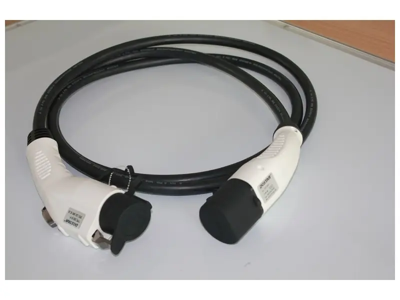
EV charging cable carries power between charging equipment and an electric vehicle. Flexible multicore construction brings the power conductors together with the protective-earth, auxiliary or control circuits required by the charging system.
Selected voltage configurations: 450/750 V AC and 1000 V DC.
XWA offers made-to-order EV charging cable with custom connector and terminal-harness options. Supply is arranged to the project configuration rather than from stock.
AC and DC charging cables have different core arrangements
The power circuit and the connector interface determine which conductors belong inside the cable.
AC charging cable construction
AC charging leads combine the selected phase conductors with a protective-earth conductor and the control circuit required by the equipment. A compact assembly helps keep the cable manageable during connection, disconnection and storage.
For an AC lead, we start with the phase arrangement and connector pin layout. That keeps the power cores, earth path and control connection coordinated from the cable through to the finished assembly.

DC charging cable construction
DC charging designs use positive and negative power conductors alongside the auxiliary and signal circuits specified by the charging equipment. Larger power cores carry the main charging current; the smaller circuits serve their separate control or auxiliary functions.
Screened signal pairs and overall screening are configuration options where the system design calls for them. The illustrated DC layout shows a non-liquid-cooled construction; liquid-cooled charging leads use a separate cable and cooling design.
EV charging cable voltage and core configurations
AC reference configurations: 450/750 V. DC reference configurations: 1000 V DC. Each row describes a separate cable arrangement.
| Charging duty | Reference core schedule (mm²) | Circuit arrangement |
|---|---|---|
| 450/750 V AC | 3 × 2.5 + 1 × 0.75 | Three main cores, including protective earth, plus one control core |
| 450/750 V AC | 3 × 6 + 1 × 0.75 | Three main cores, including protective earth, plus one control core |
| 1000 V DC | 2 × 16 + 2 × 4 + 2 × 0.75 | Two power cores, two auxiliary cores and two small control/signal cores |
| 1000 V DC | 2 × 35 + 2 × 4 + 2 × 0.75 | Two power cores, two auxiliary cores and two small control/signal cores |
| 1000 V DC | 2 × 70 + 2 × 6 + 2 × (2 × 1.5) | Two power cores, two auxiliary cores and two signal pairs |
| 1000 V DC | 2 × 95 + 2 × 6 + 2 × (2 × 1.5) | Two power cores, two auxiliary cores and two signal pairs |
Recommended reference configurations. Final supply dimensions and electrical data follow the agreed XWA cable and assembly specification. Charging current depends on conductor temperature, cable routing, cooling and the connector rating.
Materials and operating conditions
| Component or condition | Selected reference family |
|---|---|
| Conductor | Flexible copper conductors in a multicore assembly |
| Insulation | TPE in the selected AC/DC reference constructions |
| Outer sheath | TPE or TPU, selected for the specified construction |
| Ambient operating range | −40°C to +50°C for the selected TPE/TPU reference family |
| Signal arrangement | Individual control cores or paired signal cores; screening follows the circuit design |
| Supply | Made to order; connector and terminal-harness customization available |
Ambient temperature describes the environment around the lead, while conductor temperature describes its internal operating condition. Cable and connector thermal limits work together in the finished charging assembly.
Custom connectors, finished lengths and terminal harnesses
A charging lead is used as an assembly: its usefulness depends as much on the connector and cable entry as on the conductor size. XWA can discuss custom connector and terminal-harness requirements alongside the cable order.
Connector interface
The vehicle inlet and charging-equipment connection define the mating arrangement, power contacts, protective-earth path and control contacts.
Cable entry and handling
Finished cable diameter, entry sealing and strain relief belong together. Cable length and routing also influence how easily the lead can be handled and stored.
Harness details
Terminal type, branch lengths, breakout positions and the connection drawing define a customized harness. These details are developed with the required electrical configuration.
Our preference is to settle the cable and connector together, rather than select them independently and resolve the fit at assembly. That gives the project a clearer specification for both the flexible lead and its terminations.
Charging cable standards and application scope
| Reference | Application scope |
|---|---|
| EN 50620 | Charging cables carrying power and, where required, communication to electric vehicles |
| IEC 62893-3 | AC charging cables for charging modes 1, 2 and 3; rated voltages up to 450/750 V |
| IEC 62893-4-1 | Mode 4 DC charging cables without a thermal management system |
| IEC TS 62893-4-2 | Mode 4 DC charging cables intended for a thermal management system |
These references distinguish the charging duties. The 1000 V DC configurations above describe the selected reference family, rather than the maximum voltage covered by every standard.
Typical project discussions include charging-equipment connections, depot charging leads and customized charging assemblies. Vehicle interface, duty cycle and the installation environment shape the finished product.
Explore XWA cable manufacturing and our H1Z2Z2-K solar cable for photovoltaic DC connections.
EV charging cable questions
Is EV charging cable available from stock?
EV charging cable is made to order. Send the cable configuration and required quantity so XWA can discuss the supply arrangement.
Can XWA customize the connectors?
Yes. Custom connector and terminal-harness options can be discussed using the connector interface, pin assignment, finished length and assembly drawing.
Does this page include liquid-cooled charging cable?
The core schedules on this page describe conventional charging cable constructions. A liquid-cooled lead is developed as a separate cable, connector and thermal-management system.
Discuss an EV charging cable project with XWA
Send your AC or DC charging requirement, voltage, cable schedule, finished length and quantity. Include a connector drawing or interface reference when an assembled lead is required.