
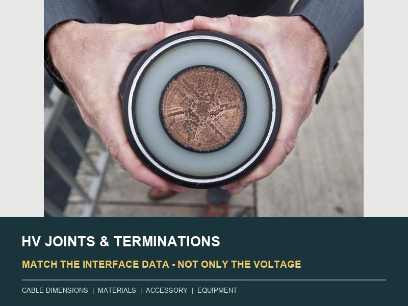
A high-voltage cable joint or termination is not selected by voltage class and conductor area alone. Those values identify an accessory family, but they do not prove physical or electrical compatibility. The final match depends on conductor construction, actual insulation dimensions, screen preparation, and interface materials. It must also cover the metallic sheath, sealing, mechanical duty, connected equipment, and qualification evidence.
This distinction matters because a factory-made cable has a nearly uniform radial insulation system. Cutting it for a joint or termination interrupts that geometry. The accessory must reconstruct the current path, insulation, and electric-field control. It must also restore the earth or sheath path and environmental protection without an unverified interface.
The uniform cable field ends at the first cut.
Inside an extruded HV cable, the conductor screen, XLPE insulation, and insulation screen form continuous concentric layers. At an accessory, crews remove or interrupt those layers. A stress-control component must guide the electric field through a new geometry while remaining in intimate contact with the prepared insulation surface.
The same operation introduces material boundaries. XLPE may contact silicone rubber, EPDM, lubricant, semiconductive components, connector metal, sealing materials, or other accessory parts. CIGRE TB 968 defines compatibility through sustained performance at contacting materials. The interface must meet its electrical, thermal, and thermomechanical duties over time. Its CIGRE material-interface overview also identifies surface smoothness, interface pressure, lubricant, and contamination as influential parameters.
For that reason, “suitable for 132 kV, 1,000 mm²” remains incomplete. A 1,000 mm² conductor may use different materials, strand arrangements, segmental constructions, compacting levels, diameters, and connector preparation. The insulation system may also differ in diameter, screen treatment, material formulation, and dimensional tolerance.

Trace a joint through five restored functions.
A straight joint connects two cable lengths, but the visible conductor connector is only one part of the task. The joint must restore five functions across the cut.
- Current path: the connector must fit the conductor material, construction, dimensions, surface preparation, current duty, short-circuit duty, and approved installation method.
- Main insulation: the joint insulation and cable insulation must form a stable dielectric interface across the permitted cable-diameter range and thermal cycle.
- Electric-field control: the screen cut, stress cone or equivalent grading system, and semiconductive interfaces must follow the accessory design.
- Metallic and earth path: copper wires, metallic sheath, sectionalizing insulation, bonding leads, and earth continuity must match the circuit bonding scheme.
- Environmental protection: the completed assembly must restore oversheath protection, longitudinal sealing where specified, and resistance to the joint-bay environment.
A mismatch in any one function can remain hidden after assembly. A connector may carry current but create local thermal or mechanical stress. A stress-control body may fit nominally but operate outside its intended interface-pressure range. A joint may pass a visual inspection while its metallic-sheath restoration conflicts with the cross-bonding design.
The cable schedule therefore needs more than nominal descriptors. The XWA 76/132(145) kV cable range provides voltage-class context, but the accessory release still requires the actual approved cable construction and dimensions.
A termination has two masters.
A termination must match the cable on one side and the connected network equipment on the other. Cable-side checks resemble a joint: conductor connection, insulation diameter, screen cut, stress control, metallic sheath, sealing, and mechanical support. Equipment-side checks depend on whether the destination is an outdoor air termination, GIS, transformer interface, or another defined assembly.
For an outdoor termination, the system basis may include pollution severity, creepage concept, altitude, and insulator material. Weather exposure, terminal hardware, mechanical loads, support, and earthing can also govern. These inputs do not come from the cable diameter.
For a gas-immersed termination above 52 kV, IEC 60840 requires additional design and testing according to IEC 62271-209 within the applicable scope. IEC 62271-209 covers the connection assembly between the cable termination and gas-insulated metal-enclosed switchgear. Its scope includes fluid-filled and dry-type arrangements with a separating insulating barrier. Interface dimensions, pressure boundary, mechanical forces, safety responsibilities, and limits of supply must agree across the equipment and accessory documentation.
The interface cannot be resolved by assigning every uncertainty to the accessory supplier. The cable construction, termination design, GIS or transformer arrangement, civil support, earthing, and installation method belong to different packages. One controlled interface drawing must show how they meet.
The data handover must describe the real surfaces and boundaries.
The following handover is deliberately organized by physical interface rather than by department. It exposes missing data before an accessory model or manufacturing drawing receives approval.
| Physical interface | Cable or system data to exchange | Accessory or equipment confirmation |
|---|---|---|
| Conductor to connector. | Material, nominal area, construction, segmental or stranded form, actual diameter range, current and fault duty. | Connector type, fit range, preparation, tooling, compression or tightening method, installation record. |
| Prepared insulation to stress control. | Diameter over insulation, tolerance, ovality where relevant, insulation material, screen type, stripping and surface requirements. | Permitted dimensional window, interface pressure basis, preparation dimensions, lubricant and cleanliness rules. |
| Screen cut to grading system. | Insulation-screen construction, bonded-screen removal method, permitted surface condition, geometric preparation limits. | Stress-control position, preparation template, defect limits, inspection method. |
| Metallic sheath to bonding assembly. | Sheath or screen material and area, fault duty, bonding diagram, sectionalizing requirement, earth-continuity arrangement. | Sheath restoration, bonding lead and link-box interface, insulation level, test access. |
| Oversheath to environmental seal. | Oversheath material and diameter, water-blocking design, joint-bay or termination environment, corrosion and flood basis. | Seal range, outer protection, water test or inspection method, temporary and permanent sealing instructions. |
| Termination to connected equipment. | Terminal arrangement, phase spacing, support, conductor forces, earthing, equipment drawing and operating environment. | Flange or plug-in dimensions, terminal hardware, mechanical limits, pressure boundary, limit of supply. |
Nominal dimensions should never replace the approved ranges. The accessory design needs the minimum and maximum values that can occur after cable manufacture, handling, and preparation. The cable drawing should use the same measurement definitions as the accessory drawing; otherwise, two identical numbers may describe different surfaces.
Three mismatch patterns can survive a datasheet review.
The diameter fits, but the material interface changed.
A stress-control body may cover the stated diameter while a change in insulation, semiconductive material, lubricant, or manufacturing process alters interface behavior. CIGRE TB 968 notes that deviations from a proven system need technical assessment; development tests can provide supporting evidence when a change does not qualify automatically as substantial. The decision needs a documented compatibility basis, not an assumption that equal dimensions mean equal performance.
The cable and accessory fit, but the equipment boundary does not.
A termination can match the prepared cable yet conflict with GIS enclosure dimensions, transformer terminal forces, phase spacing, support height, pollution requirements, earthing, or the agreed limit of supply. This mismatch often appears late because cable, accessory, and substation drawings advance on separate schedules. A common interface drawing should precede final release.
The design is compatible, but the site preparation leaves its range.
The approved system assumes defined preparation dimensions and surface quality. Excessive semiconductive-screen removal, scratches, steps, contamination, wrong lubricant, uncontrolled humidity, incorrect connector installation, or transferred mechanical load can create an interface that qualification never represented. Workmanship controls therefore protect the design rather than supplement it cosmetically.
Qualification is a boundary map, not a report title.
IEC 60840 and IEC 62067 treat HV and EHV products as cable systems that include accessories. The selected standard depends on rated voltage and scope; the related XWA explanation of IEC 60840 and IEC 62067 boundaries gives that distinction. For accessory review, the more important question is whether the offered cable, joint, and termination remain inside the tested design family.
A useful qualification map identifies the tested cable construction, conductor, insulation system, and dimensions. It also records joint and termination types, materials, voltage class, test arrangement, and permitted extension rules. The map identifies changes that require engineering assessment, development evidence, or renewed testing.
IEEE 404:2022 provides ratings and test requirements for joints used with shielded extruded and laminated dielectric cables from 2.5 kV to 500 kV. It also addresses metallic-shield and jacketing components. This is useful in IEEE-based specifications, but an IEEE 404 reference does not replace the project voltage standard, exact cable-accessory compatibility, equipment interface, or installation control.
The broader XWA 66-500 kV high-voltage cable portfolio shows the range of voltage classes. Each actual circuit still needs its own accessory matrix because qualification evidence belongs to a defined system, not to the portfolio as a whole.
Workmanship becomes part of the insulation system.
Most HV joints and terminations combine factory-made components with site assembly. The final dielectric interface does not exist until crews prepare the cable and install the accessory. Installation records must therefore show that the field assembly stayed inside the design instructions.
The work plan should control storage, packaging condition, component identity, and environmental limits. It should define the work enclosure, cleanliness, cable position, preparation tools, and screen removal. Further controls cover insulation inspection, connector operation, stress-control position, seals, earthing, and final checks. Measurements should use calibrated tools where the procedure requires them. Hold points should occur before concealed interfaces disappear.
Installer competence matters, but a name or certificate cannot replace process evidence. Useful records identify the accessory, cable, drawings, and instruction revisions. They capture preparation dimensions, connector tooling or tightening, specified environmental readings, and material batches. They also retain inspection acceptance, deviations, and photographs of defined hold points. The record should allow a later reviewer to reconstruct what the design intended and what the site actually assembled.
Mechanical support also belongs in the interface review. Cable thermal movement, conductor forces, equipment movement, and short-circuit loads must not impose unverified force on a joint or termination. Supports, cleats, flexible sections, and fixed points should follow the thermomechanical study rather than an accessory photograph.
Release the accessory only when one statement is true.
The exact cable construction, accessory design, equipment boundary, installation method, and qualification evidence must describe the same system. Every item must remain within its approved dimensional, material, electrical, thermal, mechanical, and environmental limits.
That statement is stronger than “voltage and conductor size match.” It forces every discipline to resolve the physical interfaces before manufacture and site work. It also creates a clear change rule: when a cable dimension, material, connector, accessory component, connected equipment, bonding arrangement, or installation condition changes, the compatibility map returns for review.
For XWA engineering alignment, start with the cable construction drawing and actual dimensional ranges. Add conductor details, the bonding schematic, and the joint and termination schedule. Equipment drawings, route environment, standard edition, and required qualification evidence complete the submission. That package supports one connected-system review without turning an educational article into a generic quotation checklist.