
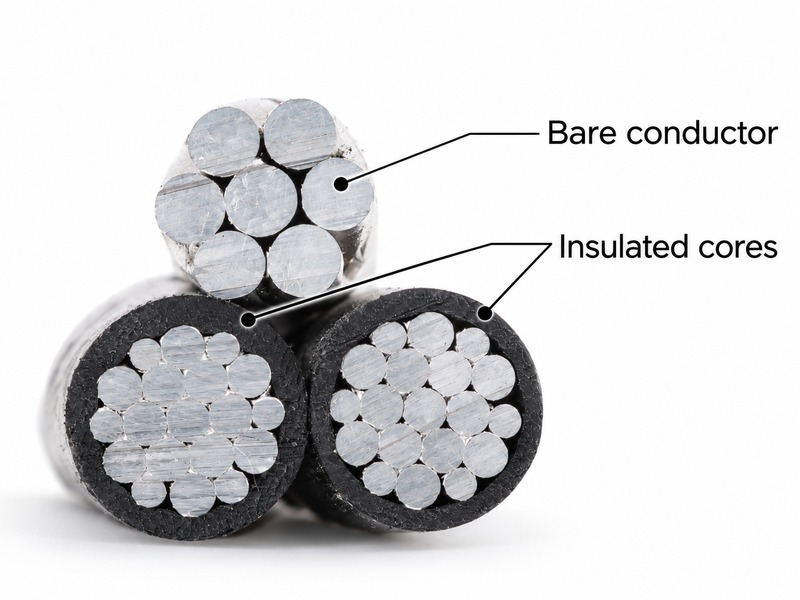
An ABC cable neutral messenger combines an electrical neutral function with the mechanical support of the bundle. That describes a neutral-messenger design, not every aerial bundled cable. Other assemblies share tensile loading across their cores, or use a supporting member whose electrical role must be separately identified. The useful distinction is therefore not simply bare versus insulated: it is which conductor completes the circuit and which member transfers loading into the supports. For XWA’s low-voltage ABC configuration, those two duties need separate data. Neutral resistance and continuity describe the electrical path; messenger strength, line loading and compatible fittings describe the support system.

The same conductor can belong to two different circuits
Consider the electrical circuit first. In a three-phase, four-wire distribution arrangement, the neutral carries the resulting current from the connected phase-to-neutral loads. Its required duty follows the network and load conditions. Calling that conductor a messenger does not reduce it to a mechanical rope.
Now follow the mechanical path. In a neutral-messenger system, the supporting member receives the bundle’s loading and transfers it through the specified suspension or tension assemblies to the supporting structure. The phase cores are carried within that assembly. The distinction matters at both an intermediate suspension point and a dead-end, where the fittings must match the intended support method.
These duties coincide in one conductor only when the design says they do. A separate steel supporting member cannot be assumed to be the neutral, while an insulated neutral cannot be assumed to carry the complete bundle’s tension. The XWA ABC cable range is the product starting point; the approved construction drawing identifies the roles within an individual bundle.
Public utility specifications make the distinction concrete. Eskom’s 240-84758170, Revision 2, describes low-voltage bundles with either a bare or insulated neutral that supports the assembly. It is a historical utility-specific specification based on SANS 1418, not a universal requirement for every ABC system.
Balanced phase currents do not make the neutral redundant
A short calculation shows why a neutral’s electrical duty cannot be judged from one balanced operating snapshot. Assume sinusoidal currents, equally spaced phase angles of 120 degrees and the same power factor on all three phases. These deliberately simplified conditions exclude harmonic currents and do not constitute a sizing calculation.
The neutral current magnitude is the magnitude of the vector sum of the three phase currents. For these assumptions:
IN = |IA + IB + IC|, where the three quantities are phasors rather than numbers added arithmetically.
- With 50 A on each phase, the three phasors cancel and the neutral current is zero.
- With 80 A on phase A and 50 A on phases B and C, the latter two combine to oppose 50 A of phase A. The remaining neutral current is 30 A.
- With an 80 A load on phase A alone, the neutral carries 80 A in this simplified circuit.
The messenger’s support duty remains in all three cases. A change in connected load changes the electrical result without changing which member holds the bundle. Conversely, a mechanically adequate supporting conductor does not establish an acceptable neutral resistance or thermal duty.
This is also why a fixed rule such as “the neutral is always half the phase size” is inadequate. The actual neutral design must follow the applicable cable specification and network assessment. The arithmetic above explains imbalance; it does not approve a reduced neutral or establish a product ampacity.
At the support, cable design and clamp design must agree
For a self-supporting bundle, the cores contribute to supporting the assembly. That differs from transferring support through a designated neutral messenger. An accessory described only as an “ABC clamp” does not resolve the difference.
The public scopes of BS EN 50483-2:2026 and BS EN 50483-3:2026 preserve that separation. Part 2 addresses tension and suspension equipment for self-supporting systems; Part 3 addresses equipment for neutral-messenger systems, including insulated or bare neutral messengers. Their published scopes concern low-voltage ABC fittings at U0/U (Um) = 0.6/1 (1.2) kV and describe type tests. They are not a medium-voltage accessory specification or a complete line-design method.
For an insulated messenger, the interface includes the diameter over insulation and the specified insulation behavior, as well as the conductor underneath. A fitting that accommodates the diameter is not automatically qualified for the assembly’s load or temperature conditions. With a bare messenger, its construction and contact interface still need to match the approved fitting.
Minimum breaking force is another easily misread field. It describes a mechanical requirement, not a permitted stringing tension. Span, bundle mass, weather loads, sag, temperature and the supporting structures enter the line design. Dividing a breaking-force value by an arbitrary factor does not produce an approved installation schedule.
This support-system distinction also applies when reviewing an overhead cable construction alongside retained line hardware. The hardware’s compatibility must follow the proposed assembly, rather than its general product label.
Read the last number before deciding what supports the bundle
A designation such as 3 x 70 + 1 x 54.6 + 1 x 16 mm2 contains more information than a single “70 mm2 ABC” label. In the illustrated neutral-messenger arrangement, it separates three phase conductors, one supporting neutral and one auxiliary conductor.
| Designation field | Role in the illustrated arrangement | What remains to be specified |
|---|---|---|
| 3 x 70 mm2 | Three phase conductors | Material, resistance, insulation and electrical duty |
| 1 x 54.6 mm2 | Neutral messenger | Electrical resistance, mechanical properties, insulation status and fitting interface |
| 1 x 16 mm2 | Auxiliary core | Assigned circuit and identification; not a substitute for the messenger |
This is a notation example, not a recommended size combination for an unspecified route. CEB’s published 018-1:2019 specification lists this configuration and identifies a strain-bearing aluminium-alloy neutral messenger. That historical document illustrates a defined construction; it does not establish that every bundle with a smaller extra core has the same functions.
Likewise, “4 x 70” states a count and nominal areas but does not, by itself, identify the support method, conductor material or neutral connection arrangement. A photograph cannot supply those missing identities. Black insulation, ribbing and a similar-looking cut face are not evidence of alloy grade or breaking force.
The broader ABC size-selection article addresses feeder load, voltage drop and route constraints. Here, the narrower task is to establish which conductor each calculation and fitting refers to.
One finished bundle needs two sets of evidence
For a neutral-messenger configuration, the factory drawing and test schedule should keep electrical and mechanical acceptance visible as separate requirements. Neither a resistance result nor a tensile result substitutes for the other.
| Evidence | Question it helps resolve | Question it does not resolve alone |
|---|---|---|
| Conductor identification and resistance result | Does the specified neutral match its construction and electrical requirement? | Can the installed span carry the design loading? |
| Specified messenger mechanical properties and corresponding test evidence | Does the supporting member meet its defined mechanical requirement? | Is neutral resistance or load-current duty acceptable? |
| Accessory qualification for the intended support system | Does the tested cable-and-fitting interface match the proposed assembly? | Are all route loads, spans and structures acceptable? |
| Approved line design and installation schedule | Are the supplied assembly and support arrangement applied within the project design? | Were all production lots made to the approved cable construction? |
Eskom’s public specification separately lists conductor resistance, physical dimensions and supporting-conductor strength among its requirements. That separation is useful engineering logic even where a different utility specification governs. Exact test categories, sampling and acceptance limits must come from the applicable document, not from a generic ABC checklist.
At the XWA documentation interface, the neutral’s circuit identity, messenger identity and accessory reference should remain consistent across the drawing, conductor schedule and supporting evidence. Any mismatch needs resolution before the configuration is treated as complete.
A neutral is a circuit conductor, even when it is carrying the span
The word neutral must not be read as “safe to touch,” and visible insulation must not be treated as authorization to approach or work on an overhead assembly. An interrupted neutral path can alter the operation of connected phase-to-neutral loads even while the line remains mechanically supported. Inspection, connection and repair require the network operator’s approved procedures and qualified personnel.
HSE guidance on work near overhead lines provides independent safety context, including treating a line as live unless its owner confirms otherwise. Local network rules determine the actual work arrangements.
The central design requirement is straightforward: identify the member that carries current and the member that carries loading. When one neutral messenger performs both duties, its electrical specification and its mechanical support interface must both be satisfied.