
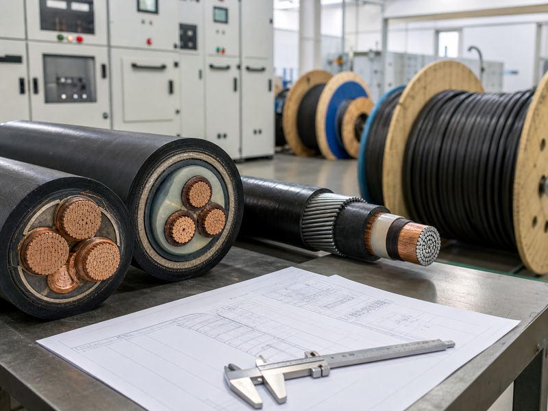
Endüstriyel Projeler için Orta Gerilim Kablo Seçimi: Şartname, Kurulum, ve Test Limitleri
Medium voltage cable selection for an industrial project is not only a voltage choice. The cable design must match the system voltage, arıza seviyesi, rota ortamı, kurulum yöntemi, metalik ekran gereksinimi, sheath and armor protection, aksesuarlar, and test plan. A medium voltage cable that looks correct by nominal voltage can still create problems if the cable route cannot meet bend radius limits, if pulling tension is not controlled, if the screen bonding method is unclear, or if terminations are installed in poor site conditions.
XWA reviews MV cable requirements from the factory and engineering side. The project specification must define the electrical duty first, then the route and installation conditions. Only after those details are clear can the construction be confirmed, including conductor size, yalıtım sistemi, metalik ekran, zırh, dış kılıf, tambur uzunluğu, ve dokümantasyon. This page updates the old MV selection article into a practical engineering reference for industrial power distribution, madencilik siteleri, yardımcı programlar, renewable plants, trafo merkezleri, and large facilities.
The first decision is the system duty, not the cable catalogue name
A medium voltage cable schedule often starts with terms such as 11 kV kablosu, 15 kV kablosu, 20 kV kablosu, veya 33 kV kablosu. These names are useful, but they do not define the complete cable. The same voltage class can appear in different network grounding systems, fault levels, route lengths, kurulum yöntemleri, ve çevresel koşullar. A cable for an indoor substation feeder faces different risks from a cable crossing a mine site, a solar plant collection circuit, or a utility distribution route.
The project electrical design should define the nominal system voltage, maximum operating voltage, yalıtım seviyesi, sıklık, faz düzenlemesi, yük akımı, kısa devre akımı, arıza süresi, and protection philosophy. These values influence conductor size, insulation rating, ekran tasarımı, ve aksesuarlar. XWA connects this review with the OG Güç Kablosu product range, but the final cable configuration still depends on the project data.
A common weak specification only states ?MV XLPE cable? veya ?medium voltage power cable.? That wording is not enough. It does not define voltage class, iletken malzeme, iletken boyutu, copper wire screen or tape screen, zırh tipi, kılıf bileşiği, yangın davranışı, su engelleme gereksinimi, or applicable standard. It also says nothing about drum length, route bend points, trench condition, sonlandırmalar, and acceptance tests. XWA treats the cable name as the starting point, not the final engineering answer.
Voltage class and insulation level must follow the network design
Medium voltage cable standards separate nominal cable names from insulation levels. A project may use an 11 kV network, but the cable designation may appear as 6/10(12) kV veya 8.7/15(17.5) kV depending on the design basis and local practice. A 33 kV circuit may use 18/30(36) kV kablosu. The exact designation must match the system voltage and the selected standard.
| Engineering item | Neden önemli? | XWA neyi onaylıyor? |
|---|---|---|
| Nominal voltage | Defines the network class and product family | 6 kV, 10/11 kV, 15 kV, 20 kV, 33/35 kV or other project class |
| Highest system voltage | Controls insulation level and standard designation | Rated voltage expression such as 6/10(12) kV veya 18/30(36) kV |
| Fault level and duration | Affects conductor and screen thermal withstand | Short-circuit current, fault time, and protection setting basis |
| Grounding method | Influences screen current, earth fault behavior, ve yapıştırma düzenlemesi | Solid grounding, resistance grounding, isolated system, or project-defined method |
| Load current and route length | Influences conductor size, ferahlık, ve voltaj düşüşü | Continuous current, kurulum yöntemi, gruplama, ortam sıcaklığı, ve voltaj düşüşü sınırı |
IEC 60502-2 is commonly referenced for extruded-insulation power cables from 6 kV'ye kadar 30 kV rated classes. It gives a standards framework for construction and tests, but it does not replace project engineering. The standard does not decide whether a site needs armor, how many route bends are acceptable, what soil thermal resistivity applies, or how accessories will be installed. Those conditions come from the project design and installation method.
Conductor size is controlled by more than ampacity
Conductor size normally starts with load current, but industrial MV feeders require more checks. Ampacity depends on installation method, ortam sıcaklığı, soil condition, gruplama, gömme derinliği, kanal düzenlemesi, termal direnç, and conductor operating temperature. A size that works in air may not work in a congested underground duct bank. A size that passes continuous current may still fail short-circuit thermal withstand or voltage-drop requirements.
Voltage drop becomes important when the cable route is long or when large motors start. Motor starting current can cause temporary voltage depression. Renewable collection systems can have long routes between inverter stations and substations. Mining and industrial plants may have routes with many bends, geçişler, and parallel feeders. XWA can provide cable construction and resistance data, while the project designer checks the final load-flow and voltage-drop calculation.
The conductor material also changes the design. Copper offers higher conductivity for the same cross-section and often supports smaller cable diameter. Aluminum reduces weight and material cost, but it usually needs a larger conductor size for the same current and voltage-drop target. The termination system must match the conductor material. Lug selection, compression method, oxide control, and joint quality all affect field reliability.

Ekran, kılıf, and armor are project-risk decisions
MV cable construction usually includes conductor screen, XLPE izolasyonu, yalıtım ekranı, metalik ekran, filler or binder where applicable, armor for mechanical protection when specified, ve dış kılıf. Each layer has a function. Removing or changing a layer without understanding the route risk can create failure points.
The metallic screen provides an earth path and helps control the electric field around the insulation system. Its design may use copper wire screen, bakır bant ekranı, or other project-defined metallic layer. The required screen cross-section depends on earth-fault current and duration. Ekran sürekliliği, ekran yapıştırma, and termination workmanship are critical in MV systems.
Armor is not automatically required for every MV cable. It is useful for direct burial, mekanik etki, rodent risk, endüstriyel alanlar, madencilik yolları, and places where excavation or external pressure may occur. It can also increase cable weight, çap, bükülme sertliği, and pulling complexity. For tray, kanal, or well-protected indoor routes, unarmored construction may be acceptable if the project specification allows it. The safer decision depends on route exposure, not on a universal rule.
| Rota durumu | Common construction direction | Engineering caution |
|---|---|---|
| Indoor substation or switchgear room | Unarmored or lightly protected MV cable may be acceptable | Sonlandırma alanı, yangın gereksinimi, and bending route remain important |
| Underground trench or direct burial | Armored MV cable or additional mechanical protection is often specified | Soil thermal condition and sheath protection must be checked |
| Industrial yard with vehicle or excavation risk | Zırh, uyarı bandı, kanal, or protective route design may be required | Mechanical protection does not remove the need for correct burial and route marking |
| Long duct bank | Unarmored or armored design depends on duct protection and pulling limits | Gerginliği çekme, yan duvar basıncı, and heat dissipation become key limits |
| Humid or water-exposed route | Water-blocking layer or sheath requirement may be specified | Sealed ends and drum storage are part of moisture control |
For projects comparing mechanical protection levels, the related XWA article on zırhlı ve zırhsız kablolar gives additional route-risk context. In an MV system, this comparison must also consider bending stiffness, aksesuar uyumu, ve kurulum ekipmanları.
Installation limits can reject a technically correct cable
MV cable selection must include constructability. IEEE and public project specifications repeatedly emphasize route planning, çekme koşulları, bükülme yarıçapı, cable support, lubrication, sealed cable ends, and inspection before energization. These items matter because MV insulation systems are sensitive to mechanical damage. A cable can pass factory tests and still fail early if the installation bends, pulls, scrapes, or contaminates the insulation system.
Minimum bend radius depends on the cable design, çap, zırh, iletken sınıfı, and standard or manufacturer data. A larger armored cable needs more space at trench corners, yükselticiler, switchgear entrances, and termination points. Pulling tension and sidewall pressure must also remain within the allowed limit. Long routes with several bends can become unsuitable unless the route uses pulling points, silindirler, kanallar, or revised drum planning.
End sealing deserves specific attention. Moisture can enter cable ends during storage, ulaşım, or site waiting time. MV cable drums should be stored and handled so the cable ends remain sealed and protected. If ends are damaged, wet, or contaminated, the termination process becomes riskier. XWA checks packing, davul işaretleri, and cable-end protection before shipment, but site handling continues the same responsibility.
Accessories are part of the cable system
A medium voltage cable does not operate alone. Fesihler, eklemler, Pabuçlar, stres kontrol bileşenleri, ekran yapıştırma parçaları, gland plates, and switchgear interfaces form the complete cable system. Many MV failures occur at accessories rather than in the factory cable length. This makes accessory compatibility a selection issue, not a late installation detail.
The cable outside diameter, yalıtım çapı, ekran inşaatı, zırh tasarımı, and conductor material must match the selected termination and joint kits. The termination environment should be clean, kuru, and controlled. Dust, nem, poor stripping, uneven screen removal, keskin kenarlar, and incorrect crimping can create partial discharge points. Bu nedenle, a cable datasheet should be reviewed together with accessory data and installation method.
When XWA reviews an MV cable requirement, the factory can confirm cable construction and dimensions. The project team or accessory supplier must confirm that the termination kit range fits those dimensions. This division of responsibility prevents a common problem: the cable arrives correctly made, but the accessory kit does not fit the insulation or sheath dimensions at site.
Factory tests and site tests answer different questions
MV cable testing should be separated into factory routine tests, type or sample test evidence, and site acceptance or commissioning tests. These groups do not replace each other. A factory routine test verifies the produced cable length before shipment. Type-test evidence supports the design basis. Site tests check handling, kurulum, aksesuarlar, and readiness before energization.
Factory checks commonly include conductor resistance, boyutsal muayene, gerilim testi, partial discharge test where required by the standard and voltage class, insulation and sheath measurements, kılıf bütünlüğü, marking inspection, ve tambur muayenesi. The exact test set depends on the agreed standard and contract specification. XWA also aligns test report wording with the cable designation, gerilim sınıfı, and order data.
Site testing may include visual inspection, süreklilik kontrolleri, yalıtım direnci, sheath testing, VLF dayanımı, çok delta, and partial discharge diagnostics depending on project practice and cable system voltage. Diagnostic tests need careful interpretation. A single test does not describe every risk. Aksesuarlar, noise conditions, kablo uzunluğu, prior service condition, and test setup can influence results. XWA'nın makalesi Sevkiyattan önce OG kablo testi explains the factory side; commissioning teams still define the final site test program.
What XWA confirms before MV cable production
XWA organizes MV cable configuration around a technical data set. This approach reduces ambiguity and keeps the cable, veri sayfası, işaretleme, test raporu, paketleme, and quotation aligned.
| Data required for configuration | Typical detail | Why it affects the cable |
|---|---|---|
| Gerilim tanımı | 6/10(12) kV, 8.7/15(17.5) kV, 12/20(24) kV, 18/30(36) kV | Yalıtım seviyesini ve test esasını tanımlar |
| Standart | IEC 60502-2 or project-defined standard | Defines construction and test framework |
| İletken | Bakır veya alüminyum, boyut, sınıf, single-core or three-core | Controls ampacity, rezistans, voltaj düşüşü, çap, ve sonlandırma yöntemi |
| Ekran | Bakır tel ekran, bakır bant ekranı, or specified metallic screen area | Toprak arızası yolunu ve aksesuar uyumluluğunu kontrol eder |
| Zırh | Çelik tel, çelik bant, alüminyum tel, veya zırhsız | Controls mechanical protection, ağırlık, bükülme yarıçapı, and pulling behavior |
| Dış kılıf | PVC, PE, LSZH, or special compound where specified | Rota maruziyetini kontrol eder, alev davranışı, aşınma, and environmental suitability |
| Kurulum rotası | Tepsi, hendek, kanal, doğrudan gömme, tünel, or industrial yard | Controls protection, thermal condition, and constructability |
| Drum plan | Tambur başına uzunluk, toplam miktar, varış noktası, packing requirement | Controls logistics, pulling section, joint count, and site handling |
The configuration data also supports product links inside the XWA site. A project using 11 kV feeders can refer to the 11kV Kablo page for voltage-specific product context. Higher distribution feeders can connect with the 33kV Kablo sayfa. The blog explains selection logic; the product pages define the supply range.
Selection mistakes that create industrial project risk
The most common mistake is treating rated voltage as the whole specification. Voltage matters, but it does not define the conductor, ekran, zırh, kılıf, kurulum, aksesuarlar, or tests. The second mistake is selecting armor without checking bend radius and pulling method. Armor can protect the cable, but it also makes installation more demanding. The third mistake is ignoring screen design and bonding. Poor screen selection can affect fault performance and accessory fit.
The fourth mistake is separating cable and termination decisions. MV cable dimensions must match terminations and joints. The fifth mistake is ignoring route heat conditions. Kanal bankaları, gruplandırılmış devreler, buried sections, and high ambient temperature can reduce current capacity. The sixth mistake is relying on one test result as proof of the whole cable system. Factory tests and site tests answer different questions, and both matter.
The best MV cable selection is therefore a controlled engineering decision. It starts with system duty, checks installation limits, confirms construction details, matches accessories, and defines the test documentation. This method is slower than selecting a catalogue name, but it produces a specification that can be manufactured, installed, test edildi, and maintained with fewer surprises.
SSS
What information defines a medium voltage cable specification?
A useful MV cable specification defines voltage designation, iletken malzemesi ve boyutu, yalıtım sistemi, metalik ekran, zırh, dış kılıf, kurulum rotası, geçerli standart, arıza seviyesi, tambur uzunluğu, ve test belgeleri. A short description such as ?MV XLPE cable? is not enough for production or installation planning.
Is armored MV cable always better than unarmored MV cable?
HAYIR. Armor improves mechanical protection where the route has burial, darbe, excavation, rodent, or industrial-yard risk. Aynı zamanda kablo ağırlığını da artırır, çap, bükülme sertliği, ve çekme zorluğu. Protected indoor routes, tepsiler, or ducts may use unarmored cable if the project specification and mechanical protection design allow it.
Why does bend radius matter for medium voltage cable?
MV cable insulation and screens can be damaged by excessive bending. The minimum bend radius depends on cable design, çap, zırh, conductor structure, ve kurulum yöntemi. Route drawings should leave enough space at trench corners, duct exits, switchgear entries, and termination zones.
Which tests matter before energizing an MV cable system?
Factory tests verify the produced cable before shipment. Site acceptance tests check the installed cable system, including handling condition, aksesuarlar, süreklilik, insulation condition, kılıf bütünlüğü, and dielectric performance. The final test program depends on the project standard, gerilim sınıfı, kurulum koşulu, and commissioning practice.
Can one MV cable design be used for all industrial projects?
HAYIR. Industrial projects differ in voltage, yük, arıza seviyesi, rota uzunluğu, kurulum yöntemi, heat environment, mekanik maruz kalma, and accessory system. A cable design that fits an indoor feeder may not fit a buried mining route or a renewable-energy collection circuit. The project specification must define the actual duty.
Mühendislik sonucu
Medium voltage cable selection works only when electrical design, route constructability, kablo inşaatı, aksesuarlar, and testing are reviewed together. IEC 60502-2 and other technical references provide the standards framework, but the project conditions define the final cable. XWA confirms MV cable configuration from voltage, orkestra şefi, ekran, zırh, kılıf, standart, rota, davul planı, and test-document requirements. Contact XWA with the project cable schedule, gerilim sınıfı, iletken boyutu, rota durumu, miktar, tambur uzunluğu, ve teknik fiyat teklifi için varış limanı.