
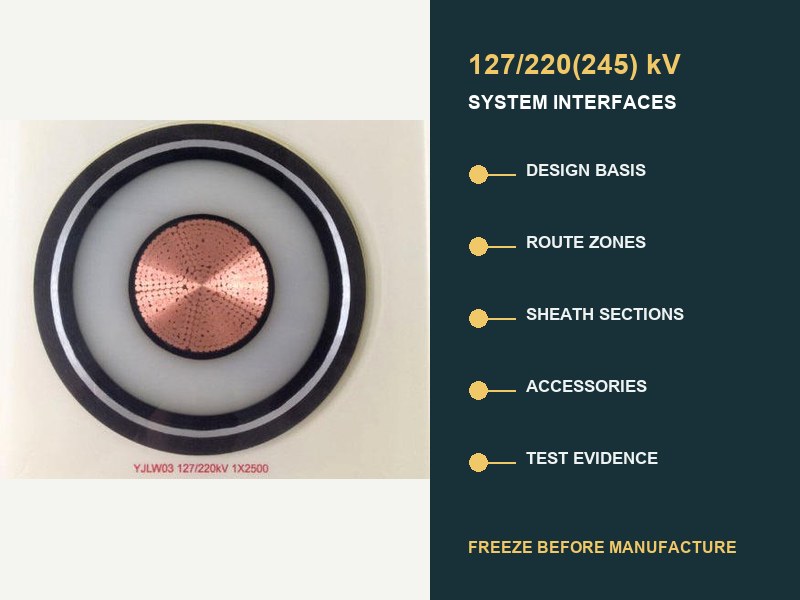
短い答え: 治療する 220 システムインターフェーススケジュールとしてのkV地中ケーブル仕様, ケーブルのデータシートとしてではない. 製造前, 電気負荷を接続します, ルートゾーン, シースセクション, アクセサリー, 工場出荷時の長さ, および受理証拠. オープンインターフェイスでは依然として間違った長さが生成される可能性があります, 互換性のないアクセサリ, アンバランスなボンディングレイアウト, または提供されたシステムをカバーしない証拠.
IEC 62067:2022 上記の押出単芯ケーブル システムの国際的な製品およびテストの管理基準です。 150 kV以下 500 通常の固定設置条件での kV 定格電圧. 普遍的なものを提供するものではありません 220 kV建設, 電流容量, シース配置, ドラムの長さ, またはルート設計. これらの決定はプロジェクトのインターフェースから行われます.

仕様ではシステムを定義する必要があります, 電圧ラベルではありません
「IEC 62067 に準拠した 220 kV XLPE ケーブル」が出発点です, 完全な仕様ではない. 共通の呼称 127/220(245) kVは対地電圧を記録します, 定格システム電圧, および最大システム電圧. 継続的な負荷についてはまだ何も書かれていません, 過失義務, 導体材料, ルート損失, 防水バリア, シース故障電流, 接着方法, アクセサリー, 取り付け力, または証拠の境界線.
IEC 60183 高電圧の選択を、導体サイズを含む調整された決定として扱います, 絶縁レベル, 工事, アクセサリー, 特殊スクリーンボンディング, および環境条件. IEC 60287 次に、重要な構造を意図的に残しつつ、定常状態の定格と損失の方程式を提供します。, 環境, そして実際のプロジェクトへのサービスマージン投入の合意. これが、カタログの電流容量では閉塞できない理由です。 220 kVルート設計.
| フリーズするインターフェース | 最小制御入力 | 開いたままだと失敗する可能性があるもの |
|---|---|---|
| 電気設計の基礎. | U0/U(1つ), 頻度, 接地, 連続的および周期的な負荷, 緊急勤務, 故障電流と期間, 力積とスイッチングデューティ. | 間違った絶縁基準, エリアコンダクター, 金属シース義務, またはアクセサリークラス. |
| ルートと熱モデル. | 設置ゾーン, 土壌/埋め戻しデータ, ダクト, トンネルの空気, 深さ, 間隔, 形成, 交差点, 隣接する熱源. | 未検証の電流定格または局所的な熱ボトルネック. |
| ケーブル構造. | 導体, XLPEシステム, 水を遮断する, 金属シース, アウターシース, 火災または環境宣言. | 路線に合致しない工事, 故障, 水, または界面の状態. |
| シースシステム. | ボンディングの概略図, セクションの長さ, 接地, リンクボックス, ボンディングリード, SVL, 定常電圧および過渡電圧の研究. | 循環損失, 危険なシース電圧, または不適切な断熱調整. |
| 付属品. | ジョイントタイプ, 終端タイプ, 接続機器, 寸法, 材料, フィールドコントロール, 機械的インターフェースとシーリングインターフェース. | 認定されたシステム ファミリ以外の名目上一致するアクセサリ. |
| 長さと物流. | 連鎖ルート, ジョイントベイ, 引っ張る方向, ドラムの限界, 輸送封筒, 保管および取り扱い計画. | 余分なジョイント, アクセスできない湾, 不適切なドラム, または不可能なプル. |
| 証拠と受諾. | 通常版, 事前認定および型式試験エンベロープ, ルーチン/サンプルテスト, ITP, 現場記録, 敷設後のテスト. | 納入された設計または設置された回路をカバーしていないレポート. |
ルートデータは管理ゾーンとして入力する必要があります
長い地下回路に熱環境が 1 つだけ存在することはほとんどありません。. 直葬, コンクリートで覆われたダクト, 水平方向の穴あけ, 橋のアプローチ, トンネル, ジョイントベイ, 変電所のエントリ, 混雑した交差点は明確なゾーンを形成します. 各ゾーンにはチェーンが必要です, 幾何学, 熱仮定, 設置方法, および設計ステータス. 支配的な評価は、平均的なルートではなく、短い限定的なセグメントから得られる場合があります。.
別の XWA ガイド 地下ルートの制約 熱を説明する, 引っ張る, 民事効果の詳細. のために 220 kV仕様, これらの計算をルートインターフェイスレジスタに要約します。. レコードゾーンの境界, 承認された入力, 責任ある規律, 計算の改訂, 導体または構造の選択に依然として影響を与える感度.
3 つの値は明示的なソース レコードに値します: 土壌または埋め戻し材の熱抵抗率, 周囲温度または土壌温度, とケーブルの配置. 入札テーブルからコピーされた一般的な値はルート証拠と同等ではありません. 干しているところ, 季節の変化, または不確実なダクト占有率が信頼できる, 評価研究では治療法を説明する必要がある. その不確実性を 1 つの電流値の中に埋め込まないでください.
シース設計は独自のセクションスケジュールを作成します
で 220 kV, 金属シースは電気および熱システムの一部です. スクリーニングを提供します, 指定された過失義務を負う, 防水保護やアクセサリーと相互作用します. その結合配置は定常シース電圧に影響を与えます, 循環電流, 損失, 定格電流, 過電圧保護, と安全な労働条件.
一点接合, 強固な結合, およびクロスボンディングはエンジニアリングオプションです, 品質グレードではありません. シグルTB 797 AC 送電システムはそれ以上であることを強調します。 66 kV には、ケーブルに基づいたプロジェクト固有のシース ボンディング設計が必要です, アクセサリー, 設置条件, 接続されたシステム. クロスボンディングは長いものでは一般的です 220 kV ルートは、バランスの取れたマイナーセクションにより正味の誘導電圧と循環損失を低減できるためです。, しかしそれは自動ルールではありません.
| 結合の決定 | 連携が必要なデータ | 必要な記録 |
|---|---|---|
| メジャーセクションとマイナーセクションの長さ. | 連鎖ルート, 位相配置, ジョイントベイの位置, ケーブルの形状. | 実際の長さと計算された長さを含むセクション集計表. |
| リンクボックスとボンディングリード. | 位置, アクセシビリティ, 車掌勤務, 絶縁レベル, アース接続. | 設備スケジュールと終了図. |
| シース電圧リミッタ. | 電源周波数定常電圧, 一時的な研究, エネルギー義務, 断熱調整. | 研究の前提条件と選択された評価基準. |
| 金属シースのサイズ. | 故障電流, 間隔, リターンパス, ボンディングモード, 材質と温度の制限. | 施工図と連動した過失割合計算. |
| 試運転テストポイント. | セクションの分離, リンク, 地球, オーバーシースアクセス, インターフェースの監視. | 完成時の接続と一致する回路図をテストする. |
したがって、共同湾への後期変更は、民間チェーンよりも大きな変化をもたらします. マイナーセクションのバランスを乱す可能性があります, ケーブルの引き渡しの長さ, リンクボックスの場所, ボンディングリードの長さ, 引っ張りセクション, そしてテスト計画. ドラム製造をリリースする前に、インターフェースレジスタを通じて変更を返します。.
製造長さはエンジニアリング出力です
ルートチェーン数と設置分析から工場出荷長を導き出す, ドラムの最大容量だけでなく. 4 つのレイヤーを揃えた便利な長さのスケジュール: アクセス可能なジョイントベイの位置, 実行可能なプル, バランスの取れたボンディングセクション, および可搬式ドラム缶. 退職金も含まれます, 共同準備手当, ルート許容値, サンプル要件, および予備の長さに関する承認されたポリシー.
不要なジョイントにより、付属品のインターフェイスと取り付け作業が追加されます. セクションが長すぎるとドラムの質量を超える可能性があります, 輸送封筒, 引っ張り張力, 側壁圧力, または現場対応能力. したがって、最適なスケジュールは「ジョイントの最小数」だけではありません。. 電気的要件を満たす最もリスクの低い配置です。, 民事, インストール, ロジスティクス, とメンテナンスの制約を一緒に.
製造リリースでは各フェーズとドラムを識別する必要があります。, 開始チェーンと終了チェーン, 引っ張る方向, 宛先ジョイントまたは終端, 計算されたセクションの長さ, 注文された長さ, ドラムの寸法と質量, および対応する接着セクション. ドラムマークと梱包書類には、図面や現場記録と同じ識別子を使用する必要があります.
アクセサリは提供されるシステム ファミリに属している必要があります
受け入れないでください 220 kV ジョイントまたは終端は、銘板の電圧がケーブルと一致するためのみ. ケーブル絶縁直径, 画面の形状, 導体接続, マテリアルインターフェース, 電界制御がすべて重要. 熱膨張, 封印, 機械的負荷, 接続されている機器もインターフェースに影響します.
シグルTB 968 ケーブルとアクセサリのインターフェイスは電気的に重要なものであると説明されています, 熱, 材料, および熱機械境界. 表面処理, 界面圧力, 潤滑剤, 汚染管理, 材料の互換性がパフォーマンスに影響を与える可能性があります. したがって、アクセサリのデータシートには、正確なケーブル構造と寸法公差範囲が記載されている必要があります。, ジェネリックではない 220 kVファミリーラベル.
終端インターフェイスにも接続機器の基盤が必要です: 外気終端, GISインターフェース, または変圧器接続; 汚染と高度の条件; 機械的負荷; 位相間隔; サポートの手配; 該当する場合、流体または気体の境界; および端末ハードウェア. ジョイントベイには作業スペースが必要です, 環境管理, 接地, サポート, および制御された設置手順.
地図IEC 62067 提供された設計の証拠
IEC 62067:2022 ケーブル システムの要件とテストを指定します。, ケーブル, およびその範囲内の付属品. 目的別に各証拠層を確認する. 事前認定レポートは、定義されたシステム ファミリの長期的な熱電挙動に対処します。. 型式試験の証拠は定義された設計に対処します. 製造された出力に対応する定期テストとサンプルテスト. 現場の記録と設置後のテストは、組み立てられた回路に対処します. 1 つのドキュメントで他のすべてのレイヤーを置き換えることはできません.
| 証拠層 | 質問に回答しました | インターフェースチェック |
|---|---|---|
| 事前資格審査. | システム ファミリは必要な長期認定を完了していますか? | 導体を比較する, 断熱システム, アクセサリー, 寸法, 材料, 電圧クラス, および許可された拡張子. |
| 型式試験. | 定義されたケーブルとアクセサリの設計は、該当する設計テストに合格していますか? | 提供されたジョイントと終端の組み合わせが表現されていることを確認します. |
| 定期テスト. | 必要な製造長さまたは付属品はそれぞれ製造検査に合格していますか? | ドラムへのトレースレポート, 段階, 付属品のシリアルID, そして図面修正. |
| サンプルテスト. | 選択された生産特性は指定された要件を満たしていますか? | サンプリング周波数を定義する, 証人ポイント, 受け入れ, および不適合対応. |
| 設置実績. | 輸送でした, 引っ張る, 準備, ジョイント, 終了作業の管理? | リンク担当者, 環境, 測定値, 材料, 写真, そしてチェックシート. |
| 設置後のテスト. | 組み立てられた回路は承認された試運転基準を満たしていますか? | ソースの一致機能, 路線の長さ, アクセサリー, テスト接続, 方法, と合格基準. |
シグルTB 841 HV および EHV システムに対する最新の敷設後テスト ソースとその制限をレビューします。. 方法に同意する, 電圧, 間隔, ソース周波数, 診断追加, プロジェクトのテストスケジュールで接続をテストします. 回路を組み立てた後は即興で使用しないでください。.
7 つのホールド ポイントでコストのかかる後からの変更を防止
- 設計ベースのホールド: U0/Uを凍結する(1つ), 接地, 荷重ケース, 過失義務, 断熱調整, および管理エディション.
- ルートモデルホールド: チェーンを承認する, ゾーン入力, 評価モデル, 設置の計算, そして未解決の感受性.
- システム設計ホールド: ケーブル構造を承認する, 導体, 寸法, 金属シース, 防水バリア, および環境宣言.
- アクセサリインターフェイスのホールド: ジョイントを承認する, 終端, 次元エンベロープ, 接続機器, および資格マッピング.
- ボンディングホールド: セクションスケジュールを承認する, リンクボックス, 接地, SVL, 断熱調整, そしてテストアクセス.
- 長さとドラムのホールド: 配達の長さを承認する, 引っ張る方向, ジョイントベイ, ドラムの詳細, ルート許容値, と識別子.
- 品質計画の保留: ITPを承認する, レポートテンプレート, トレーサビリティ, 証人ポイント, 不適合プロセス, および試運転方法.
これらのホールド ポイントは、管理されたリビジョンと名前付きの所有者を使用する必要があります。. シグルズ 2026 ライフサイクル QA/QC 作業では、プロジェクトの初期段階での不備が製造に伝播する可能性があるため、インターフェイス管理が中心的なリスクとして特定されます。, 輸送, インストール, そして操作. したがって、クローズドインターフェイスのない署名済みデータシートは、信頼できる製造リリースではありません。.
実用的な 220 kVインターフェースレジスタ
各行に 5 つのフィールドがある場合、レジスタはコンパクトなままになります。: 要件, 検証済みの入力, 証拠の参照, 責任ある所有者, そしてステータス. 未解決の項目には、決定日とブロックされる下流の文書が表示される必要があります. 最も有用なレジスタは最長のレジスタではない; それは依存関係を可視化するものです.
- 電圧とシステム: 127/220(245) kV指定, 交流周波数, 接地, 過電圧基準, 負荷と障害のケース.
- ルート: チェーン数, ゾーン図面, 熱値, 形成, 間隔, 深さ, 民事法, 引っ張りや曲がりのチェック.
- 工事: 導体, 断熱システム, 金属シース, 防水, アウターシース, 寸法と公差.
- 付属品: 正確な接合部と終端設計, ケーブル寸法ウィンドウ, 接続機器, 設置条件.
- ボンディング: メジャーセクション/マイナーセクション, リンクボックス, リード, 地球, SVL, シース電圧と故障負荷の計算.
- 製造業: フェーズ/ドラムスケジュール, 注文された長さ, サンプル, マーキング, 点検ポイント, 輸送と保管の制限.
- 証拠: 資格マトリックス, 生産報告書, トレーサビリティ関係書類, 設置記録, 完成したままの, 試運転レポート.
よくある質問 220 kV地下仕様
IECはありますか 62067 の電流定格を定義する 220 kVケーブル?
いいえ. IEC 62067 範囲内のテストと要件を定義する. 電流定格は実際の構造によって異なります, 損失, 設置形状, 熱環境, 接着配置, そして運営義務. IEC 60287 計算方法を提供します, ユニバーサルカタログ値は 1 つではありません.
クロスボンディングはすべての製品に必須ですか 220 kVルート?
いいえ. エンジニアは回路のシース システムを設計する必要があります. クロスボンディングは長いルートに適していることが多い. シングルポイントまたはソリッド配置は、特定のセクションの長さと条件に適合する場合があります. 決定には誘導電圧が必要です, 損失, 故障, 一時的な, 接地, およびメンテナンス分析.
ケーブル製造後までジョイントベイの位置は開いたままにできますか?
それは大きなリスクを生み出す. ジョイントベイで搬送長さを制御, 引っ張りセクション, 接着部バランス, リンクボックスの場所, 付属品の数量, そしてサイトアクセス. 承認された公差と変更方法が存在しない限り、暫定位置は最終的なドラムのリリースをブロックする必要があります.
事前認定レポートは納入された回路を証明しますか??
定義された認定システム ファミリをサポートします. 提供された構造とアクセサリをそのファミリとその拡張ルールにマッピングします。. 生産, インストール, 証拠の委託は引き続き別途必要です.
最終的な技術提出物に含まれるもの?
提出はケーブルスケジュールに合わせて行う必要があります, 建設図面, アクセサリインターフェイス, 結合研究, 評価レポート, 配送期間のスケジュール, 資格マトリックス, ITP, 生産報告書, 設置記録, 竣工図, 1 つのリビジョン管理されたインデックスに基づくインストール後のテスト レポート.
工学的な結論
信頼できる 220 kV 地中ケーブル仕様はインターフェース制御文書です. IEC 62067 システムテストの基礎を確立します. プロジェクトのパフォーマンスは電気負荷間のリンクにも依存します, ルートゾーン, 工事, 金属シース, アクセサリー, 長さ, インストール, そして証拠. すべてのドラムとアクセサリに設計入力からルート位置までの追跡可能なパスがある場合にのみ製造をリリースします。. 同じパスで認定エンベロープを試運転記録に接続する必要があります.
関連する XWA 127/220(245) kV製品範囲 電圧クラスと構造コンテキストを提供します, 一方、より広い 高電圧ケーブルのポートフォリオ 内に置きます 66-500 kVシステム範囲. プロジェクト固有のシース設計に関する中立的なエンジニアリング ガイダンス用, を参照してください CIGREの技術概要.
を提出してください 220 kVインターフェーススケジュール
エンジニアリングレビュー用, U0/Uを提供します(1つ), 周波数と接地, 継続的および緊急の荷重ケース, 故障電流と期間, ルートチェーンとサーマルゾーン, 形成と民事法, 絆のコンセプト, ジョイントベイと終端インターフェイス, 必要な IEC エディション, 資格と試験の要件, 納品数量, そして目的地. XWAパワー & ケーブルは提案された構造を調整できます, アクセサリインターフェースデータ, 製造長さ, 承認されたシステムベースの証拠スケジュール. 技術インターフェースの終了後に最終的な機能が確認される.