
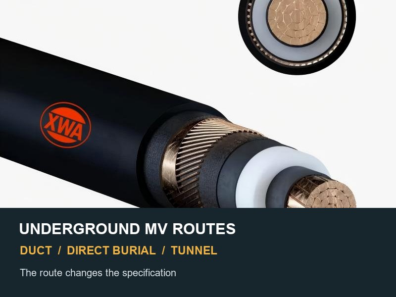
Risposta breve: un cavo sotterraneo di media tensione richiede più della tensione e della dimensione del conduttore. Inizia dividendo il percorso in sepoltura diretta, banche dei condotti, tunnel o trincee, iscrizioni dell'edificio, sezioni verticali, baie congiunte, e tratti bagnati. Ogni sezione cambia diversi compiti. Questi includono gli input termici, protezione dall'acqua e meccanica, comportamento al fuoco, supporto, superare i limiti, incollaggio dello schermo, e interfacce accessorie.
La parola metropolitana descrive la posizione del circuito. Non definisce la struttura di un cavo. Riempimento termico, un condotto pieno d'acqua, e le tacchette in un tunnel ventilato creano condizioni operative diverse. Trattarli tutti e tre come un unico ambiente può rendere un cavo valido inadatto al percorso effettivo.
Inizia con i segmenti del percorso, non una descrizione del catalogo
Un utile rilevamento del percorso converte le condizioni civili in decisioni sul sistema di cavi. Mappa il contatto con il suolo, ingressi dei condotti, l'attrezzatura si alza, incroci, zone antincendio, e sezioni accessibili. Queste transizioni spesso controllano le specifiche finali.
| Segmento di percorso | Domande di ingegneria dominante | I campi delle specifiche potrebbero cambiare |
|---|---|---|
| Sepoltura diretta. | Resistività termica del suolo, variazione di umidità, danno esterno, biancheria da letto, esposizione chimica, e riparare l'accesso. | Guaina esterna, barriere d'acqua, protezione meccanica, protezione dalla corrosione, ipotesi di ampiezza, e segnaletica del percorso. |
| Banca del condotto. | Diametro del condotto, si piega, attrito, tirando la lunghezza, condotti di ricambio, accumulo di acqua, e interazione termica tra i circuiti. | Diametro esterno del cavo, superare i limiti, attrito e tenacità della guaina, lunghezza del tamburo, disposizione dei condotti, e modello di rating. |
| Trincea o tunnel accessibile. | Temperatura dell'aria, ventilazione, propagazione del fuoco, fumo, spaziatura del supporto, ritenuta di cortocircuito, drenaggio, e accesso. | Prestazioni del fuoco, sistema di tacchette, formazione, materiali di supporto, ipotesi di ampiezza, e proprietà della guaina. |
| Sezione verticale. | Peso del cavo, movimento assiale, carico di supporto, geometria di piegatura, e carico di terminazione. | Dovere di tacchette, spaziatura del supporto, dettagli dell'allegato, lunghezza massima non supportata, e disposizione degli accessori. |
| Baia congiunta o zona di terminazione. | Spazio di lavoro, lunghezza diritta, legare i cavi, controllo dell'umidità, spaziatura di fase, e testare l'accesso. | Interfaccia accessoria, incollaggio dello schermo, punti di prova della sovraguaina, lunghezza del cavo, e sequenza di installazione. |
CEI 60502-2 copre cavi di alimentazione con isolamento estruso a posa fissa da 6 kV fino a 30 kV. Si occupa di costruzione, dimensioni, e test. Il suo campo di applicazione esclude anche condizioni speciali come il servizio sottomarino. Le condizioni del percorso rimangono quindi input del progetto, anche quando il cavo stesso è conforme allo standard di prodotto.

L'interramento diretto rende il terreno circostante parte integrante del progetto elettrico
In una sezione interrata direttamente, il calore attraversa l'isolamento, schermi, guaina, biancheria da letto, riempimento, e suolo nativo. La corrente nominale continua pertanto non è una proprietà permanente del catalogo. Il calcolo utilizza il limite di temperatura del conduttore, fattore di carico, temperatura del suolo, resistività termica, profondità di sepoltura, spaziatura del circuito, fonti di calore, e perdite di legami. Potrebbe anche essere necessaria una valutazione dell'essiccazione del suolo.
CEI 60287-3-1 distingue la sepoltura diretta, condotti, trogoli, tubi d'acciaio, e installazioni in aria. Si rileva inoltre che le condizioni nazionali o di progetto possono sostituire le condizioni generali di riferimento. Non trasferire una tabella di portata su un percorso con geometria diversa, profondità di sepoltura, suolo, o ipotesi di riempimento.
Il riempimento termico può ridurre l'incertezza quando la specifica ne controlla le proprietà. Definire il valore del progetto, posizionamento, compattazione, ipotesi di umidità, metodo di prova, e trattamento agli incroci. Denominare un materiale senza un requisito termico verificabile non controlla la classificazione del cavo.
La protezione meccanica è una decisione di percorso
L'armatura non è un sinonimo automatico di servizio sotterraneo. La sepoltura diretta può giustificare un'armatura metallica, protezione non metallica, lastre, condotti agli incroci, o una combinazione. La scelta dipende dal rischio di scavo, movimento del suolo, roditori, corrosione, perdite indotte, regole locali, e strategia di riparazione. I circuiti CA unipolari necessitano di particolare attenzione perché l'armatura ferromagnetica può creare perdite o riscaldamento inaccettabili.
Un cavo non armato può essere adatto a un robusto sistema di canali. La progettazione civile deve fornire la protezione richiesta, e le regole del progetto devono consentire l'accordo. Indica cosa protegge ogni segmento del percorso invece di aggiungere armature per abitudine.
Le sponde dei condotti spostano il rischio dai danni da seppellimento alla trazione e al calore
Un condotto protegge dal contatto diretto con il suolo. Introduce inoltre interfacce che possono danneggiare un cavo prima della messa sotto tensione. Il disegno del percorso richiede il diametro e il materiale del condotto, raggio di curvatura, cambiamenti di direzione, camere, articolazioni, direzione di trazione, pulizia, e gestione dell'acqua.
Il diametro esterno del cavo deve lasciare uno spazio adeguato dopo aver tenuto conto dell'ovalità, giunti dei condotti, e si piega. I calcoli di tiro coprono la tensione del conduttore, pressione sul fianco, attrito, dovere di tirare gli occhi o di immagazzinare, compatibilità con i lubrificanti, e controllo del verricello. Un condotto di grandi dimensioni non corregge una curva eccessiva o una sezione di tiro non realistica.
L'acqua entra comunemente nei condotti. Una guaina esterna in polietilene non fornisce un sistema completo di blocco dell'acqua. Il progetto può richiedere un bloccaggio longitudinale nella regione del conduttore o dello schermo. Un progetto con rischio di ingresso radiale può richiedere anche una barriera radiale. Tappi terminali, drenaggio della baia congiunta, sigillatura degli accessori, e i test sulla guaina rimangono controlli separati.
Tunnel e trincee sono luoghi sotterranei ma spesso installazioni aerate
Un tunnel spesso respinge il calore del cavo nell'aria. Scale, vassoi, o i tacchetti espongono inoltre il cavo a superfici e servizi vicini. Ventilazione, profilo ambientale, raggruppamento, prossimità del muro, e la formazione del circuito può dominare la valutazione. I requisiti relativi al fuoco e al fumo possono superare la resistenza all'impatto del seppellimento.
Il sistema di supporto deve sostenere un peso normale e trattenere il movimento elettromeccanico durante un cortocircuito. Morsetti per cavi, elementi di fissaggio, rotaie, parentesi, e gli ancoraggi strutturali formano un percorso di carico. Per circuiti CA unipolari, i dettagli del supporto dovrebbero evitare circuiti ferrosi chiusi attorno a una fase. Le sezioni verticali aggiungono carico assiale e non dovrebbero trasferire il peso del cavo in un pressacavo o in una terminazione per impostazione predefinita.
I termini relativi alle prestazioni antincendio necessitano di un ambito preciso. Ritardante di fiamma, bassa emissione di fumi, Limiti del gas acido alogeno, integrità del circuito, e la resistenza al fuoco utilizzano metodi di prova diversi. Una specifica del tunnel dovrebbe indicare i test richiesti e i criteri di accettazione. Il termine ampio “ignifugo” non definisce un dovere tecnico.
La protezione delle acque ha tre confini separati
I guasti legati all’acqua sono più facili da prevenire quando la specifica separa tre percorsi:
- Migrazione longitudinale. L'acqua può viaggiare lungo i fili conduttori o le interfacce dello schermo. Nastri rigonfiabili, polveri, oppure i conduttori pieni possono limitare tale movimento quando il progetto li include e li testa.
- Ingresso radiale. L'umidità può passare attraverso o attorno agli strati esterni nel tempo. Il progetto potrebbe richiedere un laminato metallico, guaina di piombo, o un'altra barriera dichiarata.
- Ingresso accessori. Sigillatura di giunti e terminazioni, tappi terminali temporanei, interfacce delle ghiandole, e i danni derivanti dalla manipolazione possono aggirare strati di cavi altrimenti idonei.
CEI 60502-2 comprende progetti con barriere d'acqua longitudinali e un test associato. Si raccomanda inoltre di considerare il rischio di ingresso radiale di acqua. Il blocco longitudinale dell'acqua non dimostra la prestazione della barriera radiale.
Le condizioni del percorso modificano anche le decisioni sullo schermo e sui collegamenti
Lo schermo metallico trasporta la corrente di carica e fornisce un percorso di guasto a terra per il servizio dichiarato. Controlla anche il campo elettrico e partecipa al sistema di legame. Controllare la sezione dello schermo rispetto alla corrente di guasto a terra e al tempo di ripristino. Coordinare il collegamento con la lunghezza del percorso, formazione, tensione di guaina, perdite, caselle di collegamento, protezione contro le sovratensioni, messa a terra, e accesso per manutenzione.
Il collegamento su entrambe le estremità può creare corrente circolante e perdite aggiuntive. Il collegamento a punto singolo può limitare le perdite circolanti ma introduce una tensione permanente sulla guaina e richiede un coordinamento controllato della messa a terra e dell'isolamento. Il collegamento incrociato può migliorare le prestazioni sul lungo percorso ma aggiunge il sezionamento, trasposizione, caselle di collegamento, e controlli sulla messa in servizio. Lo schema di collegamento deve precedere l'approvazione finale della pianificazione dei cavi.
IL Gamma di cavi di alimentazione MT fornisce il contesto della famiglia di prodotti, mentre un Costruzione N2XS2Y illustra un'opzione di media tensione rivestita in polietilene. Nessuno dei due nomi di prodotto elimina la necessità di definire l'acqua, armatura, legame, fuoco, e le condizioni del percorso.
Le transizioni del percorso creano il rischio di interfaccia più elevato
Un circuito può lasciare una trincea, attraversare una strada nei condotti, salire attraverso un edificio, e terminare al quadro. Una costruzione deve soddisfare tutti i compiti compatibili. Altrimenti, il progetto dovrà suddividere il percorso con giunti e dettagli di transizione approvati.
Rivedere il raggio di curvatura, direzione di trazione, supporto, sigillatura, arresto del fuoco, tensione indotta, continuità della sovraguaina, spazio accessorio, e accesso per ispezione. La guida a Raggio di curvatura e tensione di tiro del cavo MT spiega i controlli della forza agli ingressi dei condotti e alle curve.
IEEE 525-2025 progettazione dei cavi della sottostazione dei telai, installazione, e protezione come un unico sistema destinato a ridurre al minimo i guasti e le loro conseguenze. Questa visualizzazione del sistema è particolarmente utile per le voci di edifici e sottostazioni, dove civile, cavo, supporto, fuoco, legame, e le responsabilità di licenziamento si incontrano.
Una pianificazione dei cavi basata sul percorso è più utile di una designazione breve
Il programma finale dovrebbe preservare ogni ipotesi di progettazione e installazione approvata.
- Base elettrica: tensione del sistema, U0/U(Uno), frequenza, livello di isolamento, carico continuo, carico di emergenza, limite di temperatura del conduttore, corrente di guasto a terra, durata, e base di cortocircuito.
- Costruzione di cavi: materiale e classe del conduttore, dimensione del conduttore, Isolamento XLPE, schermi conduttori e isolanti, tipo e area dello schermo metallico, strati che bloccano l'acqua, barriera radiale dove richiesto, biancheria da letto, armatura, guaina esterna, e proprietà del fuoco.
- Modello di percorso: lunghezze dei segmenti, sepoltura diretta, condotti, trogoli, gallerie o sezioni aeree, rialzi verticali, incroci, baie congiunte, e luoghi di terminazione.
- Apporti termici: temperature del suolo e dell’aria, resistività termica del terreno, profondità di sepoltura, riempimento, geometria del condotto, spaziatura del circuito, raggruppamento, fattore di carico, perdite di legame, e fonti di calore vicine.
- Limiti di installazione: diametro finito e tolleranza, massa del cavo, raggio minimo di curvatura per fase di installazione, massima tensione di trazione, pressione sul fianco, lunghezza del tamburo, tirando l'occhio, e metodo di sigillatura.
- Interfacce e record: dati congiunti e di cessazione, diagramma di legame, caselle di collegamento, programma delle tacchette, arresto del fuoco, piano di prova, prove di sovraguaina, identificazione, e documentazione as-built.
Il funzionario Registro delle condizioni operative IEC costituisce un utile punto di verifica per la distinzione tra sepoltura diretta, condotti, trogoli, tubi, e aria. Gli input numerici effettivi provengono ancora dal progetto e dai requisiti locali applicabili.
Quattro controlli prevengono gli errori di specifica più comuni
1. Confermare che ogni valore di ampacità denomina il proprio ambiente
Una valutazione dovrebbe indicare la disposizione di installazione e le ipotesi termiche. Senza quegli input, il valore attuale non è verificabile e non può supportare una garanzia di progetto.
2. Identificare cosa fornisce protezione meccanica in ciascun segmento
La risposta potrebbe essere l'armatura, un condotto, coperture protettive, accesso controllato, profondità di sepoltura, o più misure. Un segmento di percorso vuoto rappresenta una lacuna di progettazione.
3. Separare le barriere d'acqua da una descrizione generale della guaina
Elenco guaina esterna, blocco longitudinale dell'acqua, barriera radiale, sigillatura finale temporanea, e sigillatura degli accessori come requisiti separati.
4. Congelare le interfacce civili e via cavo prima della lunghezza del tamburo
Camere, tirare le direzioni, geometria di piegatura, baie congiunte, punti di transizione, e le coordinate di terminazione determinano le lunghezze utilizzabili della sezione. L'allocazione prematura del tamburo può forzare giunti aggiuntivi o tiri impossibili.
Domande a cui si risponde lungo il percorso, non dal nome del prodotto
Ogni cavo interrato di media tensione necessita di armatura?
NO. La protezione meccanica deve corrispondere al rischio del percorso e alle norme locali. La sepoltura diretta può giustificare un'armatura o una protezione esterna, mentre un condotto o un tunnel controllato possono fornire un diverso sistema di protezione. Anche l'armatura AC single-core richiede una valutazione delle perdite e del riscaldamento.
Una guaina in PE è sufficiente per un condotto umido?
Non come una dichiarazione completa. Il progetto dovrebbe affrontare separatamente la durabilità della guaina esterna, migrazione longitudinale dell’acqua, ingresso radiale, sigillatura dell'estremità del cavo, articolazioni, terminazioni, e drenaggio del condotto.
Una tabella dei valori attuali può coprire l'interramento diretto e i condotti??
NO. Il percorso termico e la geometria di installazione differiscono. Ogni segmento del percorso necessita del modello termico applicabile e degli input di progetto, e il funzionamento è regolato dalla potenza nominale minima consentita del circuito.
Perché un tunnel può richiedere un cavo diverso da una sezione interrata?
Un tunnel può provocare un incendio, fumo, tacchetta, ventilazione, raggruppamento, e requisiti di manutenzione che non controllano una sezione interrata nel terreno. Il percorso deve utilizzare una costruzione compatibile o includere una transizione ingegnerizzata.
Quali informazioni devono essere congelate dal progetto prima della produzione?
Approvare la designazione della tensione, conduttore, schermi, barriere d'acqua, armatura e fodero, e requisiti antincendio prima della produzione. Approvare anche gli apporti termici, legame, limiti di diametro, forze di installazione, lunghezze del tamburo, accessori, test, e documenti consegnabili.
Conclusione ingegneristica
Il corretto cavo interrato di media tensione è il risultato di uno studio del percorso, non un'etichetta di catalogo. L'interramento diretto rende il terreno e il terreno di riempimento parte del sistema di classificazione. Le sponde dei condotti creano la geometria di trazione, acqua, e l'interazione termica decisiva. I tunnel spostano l’attenzione sul comportamento del fuoco, ventilazione, supporto, e contenimento dei guasti. Le transizioni combinano tutti questi rischi.
Una specifica difendibile divide il percorso e registra le condizioni di controllo per ciascun segmento. Quindi seleziona un sistema compatibile o punti di transizione deliberati. Il risultato rimane utile dalla revisione del progetto fino alla messa in servizio.
Invia il percorso e la base elettrica
Per allineamento tecnico, fornire la base elettrica e ciascun segmento del percorso. Includere la geometria dell'interramento o del condotto, dati del suolo, condizioni del tunnel, esposizione all'acqua, protezione meccanica, legame, luoghi di giunzione e di terminazione, e direzione di trazione. Aggiungi vincoli al tamburo, standard, quantità, e destinazione. Potenza XWA & Cable può preparare un pacchetto di costruzione e documentazione in base al percorso indicato.