
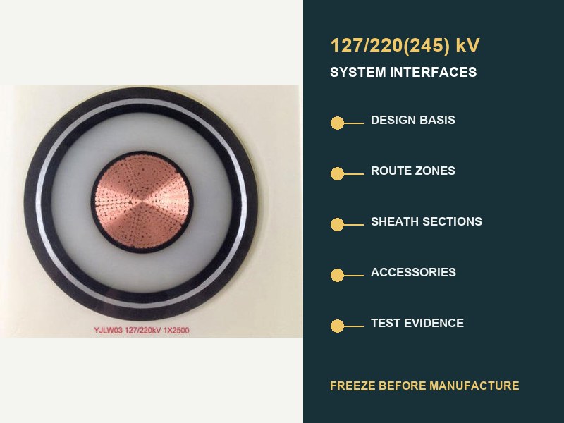
Resposta curta: Trate um 220 Especificação de cabo subterrâneo de kV como cronograma de interface do sistema, não como uma folha de dados de cabos. Antes da fabricação, conectar o serviço elétrico, zonas de rota, seções de bainha, acessórios, comprimentos de fábrica, e evidência de aceitação. Uma interface aberta ainda pode produzir comprimentos errados, acessórios incompatíveis, um layout de ligação desequilibrado, ou evidência que não cobre o sistema fornecido.
CEI 62067:2022 é a base internacional de controle de produtos e testes para sistemas de cabos extrudados de núcleo único acima 150 kV e até 500 Tensão nominal kV sob condições normais de instalação fixa. Não fornece um universal 220 construção de kV, ampacidade, arranjo de bainha, comprimento do tambor, ou projeto de rota. Essas decisões vêm das interfaces do projeto.

A especificação deve definir um sistema, não é uma etiqueta de tensão
“Cabo XLPE de 220 kV para IEC 62067” é um ponto de partida, não é uma especificação completa. A designação comum 127/220(245) kV registra tensão para terra, tensão nominal do sistema, e tensão máxima do sistema. Ainda não diz nada sobre carga contínua, dever de culpa, material condutor, perdas de rota, barreira de água, corrente de falha da bainha, método de ligação, acessórios, força de instalação, ou limites de evidência.
CEI 60183 trata a seleção de alta tensão como uma decisão coordenada envolvendo o tamanho do condutor, nível de isolamento, construção, acessórios, colagem de tela especial, e condições ambientais. CEI 60287 em seguida, fornece classificação de estado estacionário e equações de perda, deixando deliberadamente de lado a construção importante, ambiente, e entradas de margem de serviço acordadas para o projeto real. É por isso que uma ampacidade de catálogo não pode fechar um 220 Projeto de rota kV.
| Interface para congelar | Entradas mínimas controladas | O que pode falhar se permanecer aberto |
|---|---|---|
| Base de projeto elétrico. | U0/U(Um), freqüência, aterramento, carga contínua e cíclica, serviço de emergência, corrente de falha e duração, dever de impulso e comutação. | Base de isolamento errada, condutor de área, serviço de bainha metálica, ou classe de acessórios. |
| Rota e modelo térmico. | Zonas de instalação, dados de solo/aterro, dutos, túnel de ar, profundidade, espaçamento, formação, travessias, fontes de calor adjacentes. | Classificação atual não verificada ou gargalo térmico local. |
| Construção de cabos. | Condutor, Sistema XLPE, bloqueio de água, bainha metálica, bainha externa, declarações de incêndio ou ambientais. | Obra que não corresponde ao percurso, falta, água, ou condições de interface. |
| Sistema de bainha. | Esquema de ligação, comprimentos de seção, aterramento, caixas de links, ligações de ligação, SVLs, estudo de tensão permanente e transitória. | Perdas circulantes, tensão de bainha insegura, ou coordenação de isolamento inadequada. |
| Acessórios. | Tipo de junta, tipo de rescisão, equipamento conectado, dimensões, materiais, controle de campo, interfaces mecânicas e de vedação. | Um acessório nominalmente compatível fora da família de sistemas qualificados. |
| Comprimentos e logística. | Rota de encadeamento, baías conjuntas, direção de tração, limites de bateria, envelope de transporte, plano de armazenamento e manuseio. | Articulações extras, baías inacessíveis, tambores inadequados, ou puxões impossíveis. |
| Evidência e aceitação. | Edição padrão, envelope de pré-qualificação e teste de tipo, testes de rotina/amostra, ITP, registros do site, teste pós-colocação. | Relatórios que não cobrem o projeto entregue ou o circuito instalado. |
Os dados da rota devem entrar como zonas controladas
Um longo circuito subterrâneo raramente tem um ambiente térmico. Enterro direto, dutos revestidos de concreto, perfuração direcional horizontal, abordagens de ponte, túneis, baías conjuntas, entradas de subestação, e cruzamentos congestionados criam zonas distintas. Cada zona precisa de encadeamento, geometria, suposições térmicas, método de instalação, e status do projeto. A classificação dominante pode vir de um segmento curto e restritivo, em vez da rota média.
O guia XWA separado para restrições de rota subterrânea explica térmica, puxando, e efeitos civis em detalhes. Por um 220 Especificação de kV, resumir esses cálculos em um registro de interface de rota. Registrar limites da zona, entradas aprovadas, a disciplina responsável, a revisão do cálculo, e qualquer sensibilidade que ainda afete a seleção do condutor ou da construção.
Três valores merecem registros de origem explícitos: resistividade térmica do solo ou aterro, temperatura ambiente ou do solo, e arranjo de cabos. Um valor genérico copiado de uma tabela de propostas não é equivalente a evidência de rota. Onde secar, mudança sazonal, ou a ocupação incerta do duto é confiável, o estudo de classificação deve explicar o tratamento. Não enterre essa incerteza dentro de um número de ampacidade.
O design da bainha cria seu próprio cronograma de seção
No 220 kV, a bainha metálica faz parte do sistema elétrico e térmico. Ele fornece triagem, carrega dever de falha especificado, e interage com proteção contra água e acessórios. Seu arranjo de ligação influencia a tensão da bainha permanente, corrente circulante, perdas, classificação atual, proteção contra sobretensão, e condições de trabalho seguras.
Colagem de ponto único, ligação sólida, e ligação cruzada são opções de engenharia, não notas de qualidade. CIGRE TB 797 enfatiza que os sistemas de transmissão AC em e acima 66 kV requerem um projeto de ligação de bainha específico do projeto com base no cabo, acessórios, condições de instalação, e sistema conectado. A ligação cruzada é comum em comprimentos mais longos 220 Rotas de kV porque seções menores balanceadas podem reduzir a tensão induzida líquida e a perda circulante, mas não é uma regra automática.
| Decisão de ligação | Dados que devem ser coordenados | Registro obrigatório |
|---|---|---|
| Comprimentos de seção maior e menor. | Rota de encadeamento, arranjo de fase, posições conjuntas, geometria do cabo. | Cronograma de seção com comprimentos reais e calculados. |
| Caixas de ligação e cabos de ligação. | Localização, acessibilidade, dever de condutor, nível de isolamento, ligação à terra. | Cronograma de equipamentos e desenho de terminação. |
| Limitadores de tensão de bainha. | Tensão permanente de frequência industrial, estudo transitório, dever de energia, coordenação de isolamento. | Premissas do estudo e base de classificação selecionada. |
| Tamanho da bainha metálica. | Corrente de falha, duração, caminhos de retorno, modo de ligação, limites de material e temperatura. | Cálculo de taxa de falha vinculado ao desenho de construção. |
| Pontos de teste de comissionamento. | Isolamento de seção, links, terras, acesso externo, interfaces de monitoramento. | Testar conexões as-built de correspondência esquemática. |
Uma mudança tardia para uma baía conjunta, portanto, muda mais do que a cadeia civil. Pode perturbar o equilíbrio da seção menor, comprimentos de entrega de cabos, localização da caixa de link, comprimento do cabo de ligação, puxando seções, e o plano de teste. Retorne o troco através do cadastro da interface antes de liberar a fabricação do tambor.
Comprimentos de fabricação são uma saída de engenharia
Obtenha o comprimento de entrega na fábrica a partir da análise da rota e da instalação, não apenas da capacidade máxima do tambor. Uma programação de comprimento útil alinha quatro camadas: posições acessíveis de compartimentos articulados, puxadas viáveis, seções de ligação balanceadas, e tambores transportáveis. Também inclui subsídios de rescisão, subsídios de preparação conjunta, tolerâncias de rota, requisitos de amostra, e a política aprovada para comprimento sobressalente.
Juntas desnecessárias adicionam interfaces acessórias e trabalho de instalação. Seções excessivamente longas podem exceder a massa do tambor, envelope de transporte, puxando a tensão, pressão na parede lateral, ou capacidade de manipulação do site. O cronograma ideal, portanto, não é “menor número de juntas” isoladamente. É o arranjo de menor risco que satisfaz, civil, instalação, logística, e restrições de manutenção juntas.
A liberação de fabricação deve identificar cada fase e tambor, iniciar e terminar a cadeia, direção de tração, destino conjunto ou terminação, comprimento de seção calculado, comprimento ordenado, dimensões e massa do tambor, e seção de ligação correspondente. As marcas dos tambores e os documentos de embalagem devem usar os mesmos identificadores dos desenhos e registros do local.
Os acessórios devem pertencer à família de sistemas oferecida
Não aceite um 220 junta ou terminação de kV apenas porque a tensão da placa de identificação corresponde à do cabo. O diâmetro do isolamento do cabo, geometria da tela, conexão do condutor, interfaces de materiais, e o campo elétrico controla toda a matéria. Expansão térmica, vedação, cargas mecânicas, e equipamentos conectados também afetam a interface.
CIGRE TB 968 descreve as interfaces cabo-acessório como elétricas críticas, térmico, material, e limites termomecânicos. Preparação de superfície, pressão de interface, lubrificante, controle de contaminação, e a compatibilidade do material pode afetar o desempenho. A folha de dados dos acessórios deve, portanto, fazer referência à construção exata do cabo e à faixa de tolerância dimensional, não é um genérico 220 rótulo da família kV.
As interfaces de terminação também precisam da base do equipamento conectado: terminação de ar externa, Interface SIG, ou conexão do transformador; condições de poluição e altitude; carregamento mecânico; espaçamento de fase; arranjo de apoio; limite de fluido ou gás, quando aplicável; e hardware terminal. As baias conjuntas precisam de espaço de trabalho, controle ambiental, aterramento, apoiar, e um procedimento de instalação controlado.
Mapa IEC 62067 evidência para o design fornecido
CEI 62067:2022 especifica requisitos e testes para o sistema de cabos, cabos, e acessórios em seu escopo. Revise cada camada de evidência por propósito. Um relatório de pré-qualificação aborda o comportamento termoelétrico de longo prazo para uma família de sistemas definida. A evidência do teste de tipo aborda um projeto definido. Testes de rotina e de amostra abordam a produção fabricada. Registros do local e testes pós-instalação abordam o circuito montado. Um documento não pode substituir todas as outras camadas.
| Camada de evidências | Pergunta respondida | Verificação de interface |
|---|---|---|
| Pré-qualificação. | A família do sistema completou a qualificação de longa duração exigida?? | Comparar condutor, sistema de isolamento, acessórios, dimensões, materiais, classe de tensão, e extensões permitidas. |
| Testes de tipo. | O projeto definido de cabos e acessórios passou nos testes de projeto aplicáveis? | Confirme se as combinações de juntas e terminações oferecidas estão representadas. |
| Testes de rotina. | Cada comprimento ou acessório fabricado necessário passou nas verificações de produção? | Rastrear relatórios para tambor, fase, identidade serial do acessório, e revisão de desenho. |
| Testes de amostra. | As características de produção selecionadas atendem aos requisitos especificados? | Definir frequência de amostragem, pontos de testemunha, aceitação, e tratamento de não conformidades. |
| Registros de instalação. | Foi transporte, puxando, preparação, juntando, e trabalho de rescisão controlado? | Pessoal de link, ambiente, medições, materiais, fotografias, e verificar folhas. |
| Testes pós-instalação. | O circuito montado atende à base de comissionamento aprovada? | Capacidade de correspondência de origem, comprimento da rota, acessórios, testar conexões, método, e critérios de aceitação. |
CIGRE TB 841 analisa fontes modernas de teste pós-colocação e suas limitações para sistemas HV e EHV. Combine o método, tensão, duração, frequência da fonte, adições de diagnóstico, e testar conexões no cronograma de testes do projeto. Não os improvise após montar o circuito.
Sete pontos de espera evitam alterações tardias dispendiosas
- Retenção baseada em design: congelar U0/U(Um), aterramento, casos de carga, dever de culpa, coordenação de isolamento, e edições governantes.
- Espera do modelo de rota: aprovar encadeamento, entradas de zona, modelo de classificação, cálculos de instalação, e sensibilidades não resolvidas.
- Suspensão do design do sistema: aprovar construção de cabos, condutor, dimensões, bainha metálica, barreira de água, e declarações ambientais.
- Suporte de interface de acessório: aprovar juntas, rescisões, envelopes dimensionais, equipamento conectado, e mapeamento de qualificação.
- Fixação de ligação: aprovar cronograma da seção, caixas de links, aterramento, SVLs, coordenação de isolamento, e testar o acesso.
- Fixação de comprimento e tambor: aprovar comprimentos de entrega, direção de tração, baías conjuntas, detalhes do tambor, tolerâncias de rota, e identificadores.
- Suspensão do plano de qualidade: aprovar o ITP, modelos de relatório, rastreabilidade, pontos de testemunha, processo de não conformidade, e método de comissionamento.
Esses pontos de espera devem usar revisões controladas e proprietários nomeados. CIGRE 2026 O trabalho de QA/QC do ciclo de vida identifica o gerenciamento de interface como um risco central porque deficiências nas fases iniciais do projeto podem se propagar para a fabricação, transporte, instalação, e operação. Uma folha de dados assinada sem interfaces fechadas não é, portanto, uma liberação de fabricação confiável.
Um prático 220 registro de interface kV
O registrador pode permanecer compacto se cada linha tiver cinco campos: exigência, entrada verificada, referência de evidência, proprietário responsável, e status. Os itens em aberto devem mostrar a data da decisão e os documentos posteriores que eles bloqueiam. O registro mais útil não é o mais longo; é aquele que torna as dependências visíveis.
- Tensão e sistema: 127/220(245) Designação de kV, Frequência CA, aterramento, base de sobretensão, casos de carga e falha.
- Rota: cadeia, desenhos de zona, valores térmicos, formação, espaçamento, profundidade, método civil, verificações de tração e flexão.
- Construção: condutor, sistema de isolamento, bainha metálica, proteção da água, bainha externa, dimensões e tolerâncias.
- Acessórios: projetos exatos de juntas e terminações, janelas dimensionais do cabo, equipamento conectado, condições de instalação.
- União: seções maiores/menores, caixas de links, pistas, terras, SVLs, cálculos de tensão de bainha e de falha.
- Fabricação: cronograma de fase/tambor, comprimentos ordenados, amostras, marcações, pontos de inspeção, limites de transporte e armazenamento.
- Evidência: matriz de qualificação, relatórios de produção, dossiê de rastreabilidade, registros de instalação, as-builts, relatório de comissionamento.
Perguntas comuns sobre 220 especificações subterrâneas kV
A IEC 62067 definir a classificação atual de um 220 cabo kV?
Não. CEI 62067 define testes e requisitos dentro de seu escopo. A classificação atual depende da construção real, perdas, geometria de instalação, ambiente térmico, arranjo de ligação, e dever operacional. CEI 60287 fornece métodos de cálculo, nenhum valor de catálogo universal.
A ligação cruzada é obrigatória para todos 220 rota kV?
Não. Os engenheiros devem projetar o sistema de revestimento para o circuito. A ligação cruzada geralmente é adequada para rotas mais longas. Arranjos de ponto único ou sólidos podem se adequar a comprimentos e condições de seção específicos. A decisão requer tensão induzida, perda, falta, transitório, aterramento, e análise de manutenção.
As posições dos compartimentos de junção podem permanecer abertas até depois da fabricação do cabo??
Isso cria um grande risco. As baias conjuntas controlam os comprimentos de entrega, puxando seções, equilíbrio da seção de ligação, localizações de caixas de links, quantidades acessórias, e acesso ao site. Posições provisórias devem bloquear a liberação final do tambor, a menos que exista uma tolerância aprovada e um método de mudança.
Um relatório de pré-qualificação comprova o circuito entregue?
Suporta uma família de sistemas qualificados definidos. Mapear a construção e acessórios oferecidos para aquela família e suas regras de extensão. Produção, instalação, e as evidências de comissionamento permanecem separadamente necessárias.
O que pertence à submissão técnica final?
O envio deve alinhar a programação do cabo, desenhos de construção, interfaces de acessórios, estudo de ligação, relatório de classificação, cronograma de duração da entrega, matriz de qualificação, ITP, relatórios de produção, registros de instalação, desenhos as-built, e relatório de teste pós-instalação sob um índice controlado por revisão.
Conclusão de engenharia
Um confiável 220 A especificação do cabo subterrâneo de kV é um documento de controle de interface. CEI 62067 estabelece a base de teste do sistema. O desempenho do projeto também depende das ligações entre o serviço elétrico, zonas de rota, construção, bainha metálica, acessórios, comprimentos, instalação, e evidências. Liberar a fabricação somente quando cada tambor e acessório tiver um caminho rastreável desde a entrada do projeto até a posição da rota. O mesmo caminho deve conectar o envelope de qualificação ao registro de comissionamento.
O XWA relevante 127/220(245) Gama de produtos kV fornece classe de tensão e contexto de construção, enquanto o mais amplo portfólio de cabos de alta tensão coloca-o dentro do 66-500 Faixa do sistema kV. Para orientação de engenharia neutra sobre design de revestimento específico do projeto, veja o Visão geral técnica do CIGRE.
Envie o 220 Cronograma de Interface kV
Para uma revisão de engenharia, fornecer U0/U(Um), frequência e aterramento, casos de carga contínua e de emergência, corrente de falha e duração, encadeamento de rotas e zonas térmicas, formação e método civil, conceito de ligação, interfaces de junção e terminação, edição IEC obrigatória, requisitos de qualificação e teste, quantidades de entrega, e destino. Poder XWA & O cabo pode alinhar a construção proposta, dados de interface de acessório, comprimentos de fabricação, e cronograma de evidências com a base do sistema aprovado. A confirmação final da capacidade segue o encerramento das interfaces técnicas.