
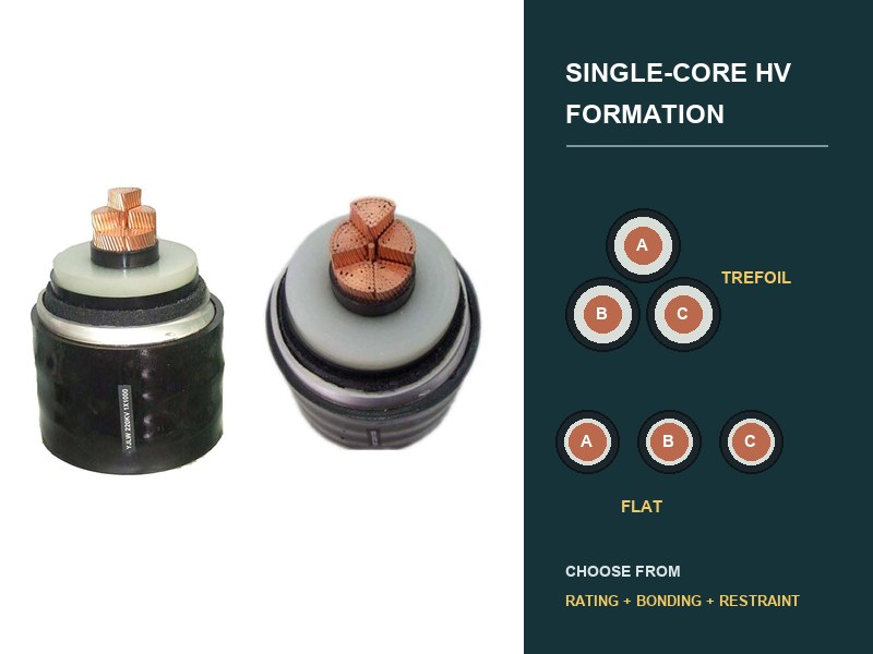
Il trifoglio è solitamente il punto di partenza più forte quando un circuito di cavo ad alta tensione single-core necessita di una geometria compatta, campo magnetico esterno inferiore, e spaziatura di fase equilibrata. La formazione piana diventa attraente quando la larghezza del percorso consente una spaziatura deliberata, dissipazione del calore o vantaggi di accesso dalla separazione, oppure l'accordo civile non può accogliere il trifoglio. Nessuna delle due soluzioni presenta un vantaggio di portata universale.
La decisione corretta richiede un modello di calcolo contenente il cavo reale, ordine delle fasi, spaziatura, mezzo di installazione, circuiti adiacenti, design con guaina metallica, metodo di legame, ciclo di carico, servizio di cortocircuito, e contenzione meccanica. Cambiare la formazione sul sito cambia quel modello; non è una regolazione del disegno innocua.
Inizia con la geometria, non una valutazione del catalogo.
Un circuito trifase trasporta correnti separate in fase. I loro campi magnetici interagiscono tra loro, con la guaina metallica di ciascun cavo, e con strutture conduttive vicine. Trefoil posiziona i tre centri dei cavi agli angoli di un triangolo compatto. La formazione piatta li posiziona su una riga, toccandoli o ad una distanza centrale definita.
Quella geometria entra in diversi calcoli collegati. Modifica l'induttanza reciproca e la tensione indotta dalla guaina. Modifica le perdite circolanti in caso di legame solido. Cambia il flusso di calore tra le fasi e il mezzo circostante. Cambia anche le forze di cortocircuito, caricamento della tacchetta, larghezza del percorso, distribuzione del campo magnetico, e accesso per l'installazione.
CEI 60287-1-1 fornisce equazioni di valutazione della corrente in stato stazionario e calcoli delle perdite, mentre la CEI 60287-2-1 affronta la resistenza termica. Entrambi richiedono input di costruzione e installazione. Non assegnano una valutazione permanente a “trifoglio” o “piatto” senza tali input.

Il trifoglio comprime il circuito magnetico.
A trifoglio, ciascuna fase ha la stessa relazione geometrica con le altre due quando la disposizione rimane simmetrica. La spaziatura compatta generalmente migliora la cancellazione dei campi magnetici trifasi esterni al gruppo. Può anche ridurre la tensione della guaina indotta rispetto a una disposizione piatta più distanziata, sebbene il risultato finale dipenda ancora dalla costruzione del cavo, attuale, frequenza, lunghezza della sezione, legame, e vicini sentieri metallici.
Il gruppo compatto utilizza una larghezza del percorso inferiore. Questo può aiutare nei tunnel, alberi, strutture a ponte, trincee strette, e sistemi di supporto. I tasselli a trifoglio possono trattenere tutte e tre le fasi come un unico gruppo quando il progetto di ritenuta testato e il calcolo dei guasti supportano tale disposizione.
La stessa compattezza può aumentare il riscaldamento reciproco. I cavi che si toccano hanno una superficie meno esposta e posizionano le fonti di calore vicine tra loro. Nell'aria, una disposizione piatta e distanziata può dissipare il calore in modo più efficace. Nel terreno o nei condotti, il risultato dipende dalla geometria della sepoltura, terreno o riempimento, resistenza termica del condotto, profondità, raggruppamento circuitale, e perdite di guaina. Il Trifoglio deve quindi vincere il calcolo completo, non solo il confronto magnetico.
La formazione piatta scambia la simmetria con la separazione.
La formazione piatta può creare più spazio tra i cavi unipolari. Una maggiore distanza può ridurre il riscaldamento reciproco e può migliorare l’accesso attorno a ciascuna fase. Può adattarsi a condotti unidirezionali separati, rastrelliere orizzontali, o trincee in cui lo spazio verticale limita un gruppo triangolare.
La geometria elettromagnetica è meno simmetrica. La fase centrale si trova alla stessa distanza da entrambe le fasi esterne, mentre ogni fase esterna vede una relazione diversa all'interno del gruppo. Tensioni indotte dalla guaina, correnti circolanti, impedenza di fase, e il campo magnetico può quindi differire in base alla posizione. Il calcolo deve mantenere l'ordine e la spaziatura delle fasi effettivi anziché sostituire il gruppo con una distanza media.
Una spaziatura più ampia aumenta anche la larghezza del percorso e può aumentare le forze elettromagnetiche tra le fasi durante un cortocircuito. I supporti e i tasselli devono corrispondere alla formazione e alle forze calcolate. Una tacchetta testata con trifoglio non può supportare automaticamente una disposizione piatta, e un test di restrizione piatta non può stabilire la prestazione del trifoglio.
Il confronto cambia con la zona di installazione.
| Condizioni del percorso | Il trifoglio tende ad aiutare quando | Il piatto tende ad aiutare quando | Il calcolo che decide |
|---|---|---|---|
| Trincea o tunnel stretto. | La larghezza del percorso e il campo magnetico esterno sono restrittivi. | L'accesso al supporto o la ventilazione necessitano di separazione e larghezza è disponibile. | Valutazione termica, campo magnetico, forze di supporto, nulla osta di manutenzione. |
| Sepoltura diretta. | Lo scavo compatto e la geometria di fase simmetrica sono preziosi. | La spaziatura definita riduce il riscaldamento reciproco nel caso del modello di terreno e riempimento verificato. | CEI 60287 valutazione con profondità effettiva, spaziatura, suolo, essiccazione, perdite, e raggruppamento. |
| Condotti separati. | La sponda del condotto può preservare la geometria triangolare e l'accesso tirante. | Una sponda orizzontale fissa già condotti di fase separati. | Resistenza termica del condotto, spaziatura, riempire, percorso di tiro, condotti di ricambio, circuiti adiacenti. |
| In aria su rack. | Dominano la moderazione compatta e il controllo sul campo. | La circolazione dell'aria e l'accesso alla fase traggono vantaggio dalla spaziatura. | Valutazione dell'aria, ambiente solare o tunnel, progettazione del supporto, forze di faglia, limiti di campo. |
| Circuiti paralleli. | Ogni circuito rimane compatto e la separazione dei circuiti è controllata. | Un ordine di fase modellato migliora il bilanciamento magnetico o utilizza la larghezza del rack disponibile. | Tutte le posizioni di fase, condivisione del carico, riscaldamento reciproco, tensioni indotte, Campo elettromagnetico, legame. |
| Transizione della formazione. | Il percorso ritorna alla geometria compatta dopo un vincolo locale. | Un incrocio o un'interfaccia di apparecchiature richiede una separazione orizzontale. | Valutazione locale, tensione di guaina, studio di trasposizione o di legame, forze, sostegno alla transizione. |
Gli esempi di calcolo indipendenti di CIGRE includono circuiti trilobati e piatti nell’interramento diretto, riempimento speciale, condotti, trogoli, aria libera, e le condizioni del fondale marino. Coprono anche diversi accordi di legame. IL esempi di calcolo indipendenti dimostrare perché la verifica del software necessita di una configurazione completa anziché di un'etichetta di formazione.
L'incollaggio può invertire il risultato termico apparente.
La guaina metallica vede la tensione indotta dalla corrente del conduttore. La grandezza e la fase dipendono in parte dalla spaziatura dei cavi e dalla posizione relativa. Il sistema di collegamento decide se tali tensioni indotte rimangono come tensione di guaina permanente, pilotare la corrente circolante, o annullare tra sezioni incrociate.
Con legame solido su entrambe le estremità, la corrente circolante nella guaina può aggiungere calore e ridurre la corrente nominale. Il compatto del trifoglio, la geometria simmetrica spesso limita tale effetto rispetto a un gruppo piatto più ampio, ma le perdite effettive devono essere calcolate. Con incollaggio a punto singolo, nella sezione principale viene evitata la corrente circolante, mentre la tensione della guaina fissa e la protezione dai transitori richiedono controllo. Il collegamento incrociato può ridurre la tensione indotta netta attraverso le sezioni minori bilanciate, ma lunghezze disuguali o cambiamenti di formazione possono indebolire la cancellazione.
Questo è il motivo per cui la formazione e il legame non possono apparire su disegni separati e non coordinati. Una transizione del percorso da trilobato a piatto modifica le relazioni reciproche. Lo spostamento di un giunto o di una casella di collegamento modifica la lunghezza della sezione. L'inversione dell'ordine delle fasi modifica l'equilibrio della tensione indotta. Ogni revisione deve ritornare allo studio della guaina e al modello di valutazione.
L'installazione deve riprodurre le coordinate calcolate.
Un modello termico che presuppone 300 I centri dei cavi mm non descrivono un percorso installato a spaziatura irregolare. Un modello di guaina che presuppone un trifoglio continuo non descrive lunghe transizioni piatte. I disegni di costruzione dovrebbero definire le coordinate del centro del cavo, tolleranze ammissibili, ordine delle fasi, supporta, tacchette, incroci, e ogni transizione di formazione.
Per la sepoltura diretta, potrebbero essere necessari distanziatori o controlli di installazione prima che il riempimento nasconda la disposizione. I disegni delle serie di condotti fissano la geometria tramite le coordinate dei condotti, ma movimento del condotto, blocco, e la sequenza di tiro necessita ancora di controllo. Nei tunnel e nei pozzi, spaziatura del supporto, orientamento della tacchetta, corrosione, movimento del cavo, e il contenimento dei guasti diventano elementi di progettazione visibili.
I cavi CA unipolari richiedono attenzione anche nei confronti dei materiali ferromagnetici. Un circuito magnetico chiuso attorno ad una fase può sviluppare corrente indotta e riscaldamento. La progettazione del supporto e della penetrazione dovrebbe utilizzare adeguate disposizioni non magnetiche o una configurazione verificata che racchiuda tutti i conduttori di fase all'interno dello stesso confine magnetico.
TBC CIGRE 889 collega l'edilizia civile con le valutazioni, incollaggio della guaina, campi elettromagnetici, tirando, comportamento termomeccanico, e pulitura. Questa visione integrata è importante durante le transizioni. Un gruppo di cavi può spostarsi dai condotti al rack del tunnel, da trilobato a piatto in prossimità delle terminazioni, o attraverso un attraversamento vincolato. Ogni transizione necessita di un coordinamento elettrico, termico, e controllo meccanico.
Un esempio di percorso mostra il motivo per cui una regola fallisce.
Consideriamo un circuito ad alta tensione che inizia in condotti orizzontali separati, entra in un tunnel ventilato, e sale a tre terminazioni esterne. La formazione piatta può essere fissata attraverso la sponda del condotto. Nel tunnel, entrambe le formazioni possono funzionare. Vicino alle terminazioni, la spaziatura delle fasi segue la geometria dell'apparecchiatura.
La scelta del trifoglio per l'intero percorso è impossibile perché i condotti e le terminazioni impongono tratti pianeggianti. Scegliere una superficie piana ovunque potrebbe sprecare la larghezza del tunnel o aumentare il campo esterno. Il compito dell'ingegneria è modellare ciascuna zona, definire le transizioni, e verificare se un progetto di collegamento rimane accettabile attraverso l'intero circuito.
Per questo esempio non è stata inventata alcuna portata perché la risposta dipende dalle perdite del cavo, dimensione del conduttore, disegno della guaina, condizioni ambientali, dati sui condotti e sul terreno, ventilazione, spaziatura, lunghezze delle sezioni, e servizio di carico. L'esempio identifica invece la sequenza corretta: bloccare la geometria del percorso, calcolare le perdite e il flusso di calore, legame coordinato, verificare la FEM e il contenimento dei guasti, quindi congelare i disegni di installazione.
Il disegno rilasciato deve riportare più di tre cerchi.
Un utile disegno della formazione registra l'identificazione delle fasi, diametro esterno e tolleranza del cavo, spaziatura centrale, orientamento, concatenamento stradale, mezzo di installazione, circuiti adiacenti, dettagli del supporto o del distanziatore, tipo di tacchetta, geometria di transizione, sezione di incollaggio, relazione casella di collegamento, e revisione dei disegni. Dovrebbe fare riferimento alla valutazione, guaina, Campo elettromagnetico, forza di cortocircuito, e studi termomeccanici che utilizzano tali coordinate.
L'XWA 64/110(123) Gamma di cavi kV E 76/132(145) Gamma di cavi kV fornire un contesto costruttivo specifico per la tensione. Il relativo articolo XWA su vincoli del percorso sotterraneo spiega il modello termico e civile più ampio. Nessuno fornisce una formazione universale; le coordinate del percorso approvate e gli studi di sistema devono farlo.
Per l'allineamento del progetto, XWA richiede la costruzione del cavo, carico e servizio di guasto, tratti di percorso, formazione e spaziatura, input del suolo o dell’ambiente, disegni di condotti o supporti, ordine di fase del circuito parallelo, costruzione con guaina metallica, schema di legame, limiti del campo magnetico, e base restrittiva. Questi input consentono a una decisione di formazione di rimanere coerente dal calcolo della valutazione fino alla produzione e all'installazione.