
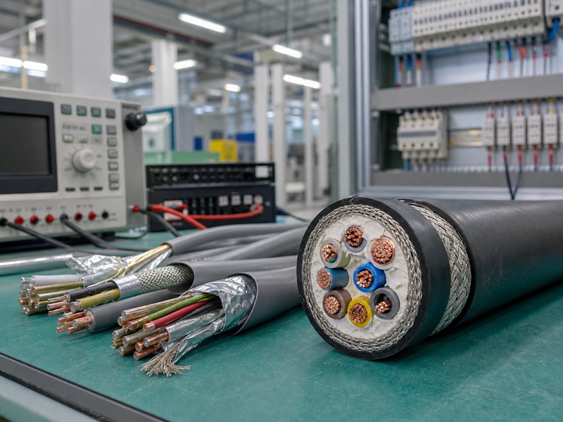
Blindage du câble de commande et sélection du numéro de noyau devrait commencer par le type de signal, niveau de tension, environnement sonore, disposition des armoires, philosophie du noyau de rechange, et méthode de résiliation. Le blindage contrôle les interférences électromagnétiques. Le nombre de cœurs contrôle le regroupement de circuits, espace d'installation, capacité de modification future, et travaux d'identification à l'intérieur des panneaux. Un câble qui semble correct en termes de tension nominale peut néanmoins créer des problèmes sur site si le blindage, regroupement de paires, numérotation des noyaux, ou le fil de décharge ne correspond pas au système de contrôle.
Du point de vue de l’usine et de l’ingénierie de XWA Cable, une spécification de câble de commande nécessite plus que “câble de commande blindé” ou “12-câble central.” Le fichier de projet doit définir la taille du conducteur, classe de chef d'orchestre, matériau isolant, identification du noyau, bouclier individuel ou global, fil de drainage, armure, gaine, exigence de flamme, tension nominale, exigence de test, longueur du tambour, et marquage. Le Câble de commande la page produit donne le contexte du produit; cet article explique la logique d'ingénierie derrière le blindage et le nombre de cœurs.
Le blindage et le nombre de cœurs résolvent différents problèmes.
Le blindage et le nombre de conducteurs apparaissent souvent dans la même demande de câble de commande, mais ils ne résolvent pas le même problème. Le blindage réduit les bruits électriques indésirables entre le câble et l'équipement à proximité. Le nombre de cœurs définit le nombre de circuits de contrôle, contacts auxiliaires, signaux, ou des conducteurs de rechange que le câble peut transporter.
Un câble blindé avec un nombre de conducteurs incorrect crée un encombrement des terminaisons ou force des passages de câbles supplémentaires. Un câble avec suffisamment de conducteurs mais sans blindage approprié peut créer une instabilité du signal à proximité des disques., moteurs, transformateurs, contacteurs, ou sources radiofréquences. La construction finale doit correspondre à la fois à l'environnement électrique et au plan de câblage du panneau..
| Question de conception. | Décision de protection. | Décision sur le numéro de base. | Données d'usine nécessaires. |
|---|---|---|---|
| L'itinéraire passe-t-il à proximité de câbles électriques ou de lecteurs? | Un bouclier global ou un bouclier en paire peut être nécessaire. | Séparez les circuits bruyants et sensibles lorsque cela est possible. | Environnement de l'itinéraire et type de signal. |
| Le câble transporte-t-il des signaux analogiques ou de bas niveau? | Une meilleure couverture du blindage et les détails du fil de drainage sont importants. | Les paires torsadées peuvent mieux s'adapter que les simples noyaux numérotés. | Type de signal et schéma de câblage. |
| Le cabinet a-t-il besoin d'une expansion future? | Le type de bouclier reste lié au risque de signal. | Les noyaux de rechange peuvent réduire les retouches ultérieures. | Liste de base et plan de base de rechange. |
| L'installation nécessite-t-elle une protection mécanique? | Le bouclier ne remplace pas l'armure. | Le nombre de noyaux affecte le diamètre et la flexion. | Armure, gaine, et méthode d'installation. |

Quand le blindage global est suffisant.
Un blindage global enveloppe l'ensemble du câble complet sous la gaine extérieure. Il aide à réduire les interférences électromagnétiques externes et fournit une couche de blindage continue pour le groupe de noyaux.. Cette construction s'adapte à de nombreux circuits de commande généraux où le câble traverse une installation industrielle, salle de contrôle, ligne de machines, ou système auxiliaire de sous-station.
Le blindage global fonctionne mieux lorsque tous les noyaux à l'intérieur du câble partagent un niveau de signal et une sensibilité au bruit similaires.. Des exemples typiques incluent le contrôle des relais, circuits de verrouillage, alimentation de commande basse tension, commande start-stop, et câblage d'état auxiliaire. Le bouclier doit avoir une couverture appropriée, continuité, et conception de terminaison. XWA peut fournir des structures de blindage globales telles que du ruban de cuivre, ruban aluminium-polyester avec fil de drainage, ou tresse de cuivre lorsque la spécification l'exige.
Quand le blindage par paire ou le blindage individuel a plus de sens.
Le blindage par paire individuelle ou le blindage par groupe de conducteurs individuel convient aux applications où les signaux à l'intérieur du même câble doivent être séparés.. Signaux analogiques, signaux d'impulsion, circuit de communication, retour du capteur, et le câblage lié à l'instrumentation peut souffrir de diaphonie si tous les circuits ne partagent qu'un seul blindage global.
Le blindage par paire ajoute de la structure et du coût. Il augmente également le diamètre du câble et le travail de terminaison. L'avantage apparaît lorsque l'intégrité du signal compte plus que la construction compacte. Dans ces cas, XWA examine le nombre de paires, torsion de paire, type de bouclier, disposition des fils de drainage, isolation, gaine, et marquage afin que le câble fourni corresponde au dessin du système de contrôle.
| Structure du bouclier. | Utilisation courante. | Force. | Limite. |
|---|---|---|---|
| Câble de commande non blindé. | Commutation simple, contact sec, itinéraires courts et propres. | Diamètre plus petit et terminaison plus simple. | Faible protection contre le bruit à proximité de sources d'interférences. |
| Blindage global en feuille avec fil de drainage. | Câblage de contrôle industriel général et d’armoire. | Bonne couverture et résiliation pratique. | Moins de séparation entre les circuits internes. |
| Bouclier tressé en cuivre. | Itinéraires nécessitant flexibilité et durabilité mécanique. | Bonne continuité et manipulation robuste. | Coût généralement plus élevé et diamètre plus grand. |
| Bouclier de paire individuel plus bouclier global. | Analogique mixte, impulsion, et signaux de commande sensibles. | Meilleur contrôle de la diaphonie. | Construction et terminaison plus complexes. |
La mise à la terre du blindage doit correspondre au système de contrôle.
Les performances du blindage dépendent de la méthode de mise à la terre. Un bouclier qui reste flottant peut ne pas contrôler le bruit comme prévu. Un blindage mal mis à la terre peut créer des problèmes de courant de circulation ou de boucle de terre indésirables.. La méthode correcte dépend de la fréquence du signal, conception de circuits, système de mise à la terre de l'équipement, et la pratique du cabinet.
De nombreux circuits analogiques et d'instrumentation basse fréquence utilisent une mise à la terre du blindage à une extrémité pour réduire le risque de boucle de terre.. Le contrôle du bruit à haute fréquence peut nécessiter une approche de liaison différente. XWA ne définit pas la philosophie de mise à la terre du système de contrôle à partir du seul câble. La construction du câble fournit le blindage, fil de drainage, et continuité; la conception du système définit la façon dont le bouclier se termine.
Le numéro de base commence par la liste des circuits.
La sélection du numéro de base doit suivre la liste des circuits, pas une habitude comme toujours utiliser un câble à 7 ou 12 conducteurs. La liste des circuits doit montrer chaque fonction de contrôle, tension, type de signal, noyau de rechange, référence de borne, et itinéraire. Cela empêche un câble de mélanger des circuits qui devraient rester séparés.
Par exemple, commande démarrage/arrêt du moteur, retour d'information sur les défauts, sélection locale-distante, arrêt d'urgence, et l'indication d'état peut apparaître dans la même armoire. Certains projets placent ces fonctions dans un seul câble multicœur. D'autres projets divisent la sécurité, analogique, et circuits bruyants dans des câbles séparés. La meilleure structure dépend du risque électrique, logique de maintenance, espace de terminaison, et normes du site.
Trop peu de cœurs et trop de cœurs créent tous deux des problèmes.
Trop peu de cœurs peuvent forcer l'ajout de câbles à un stade ultérieur, changements de jonction, ou réutilisation des noyaux pour des fonctions non représentées dans le dessin original. Cela crée un risque de documentation et rend le dépannage plus difficile. Trop de noyaux augmentent le diamètre du câble, rayon de courbure, remplissage du plateau, taille du glande, et encombrement des terminaisons. Les noyaux de rechange supplémentaires nécessitent également une identification et un traitement final..
XWA traite généralement les cœurs de rechange comme une décision technique. Un petit nombre de cœurs de rechange peuvent prendre en charge les modifications de mise en service. Un grand nombre de conducteurs de rechange peut rendre le câble plus difficile à installer et à terminer. Le fichier de projet doit définir la quantité de noyaux de rechange au lieu de la laisser à l'hypothèse d'usine..
| Choix du nombre de noyaux. | État utile. | Risque en cas de mauvaise utilisation. |
|---|---|---|
| 2 à 4 noyaux. | Commandes simples, puissance auxiliaire, ou circuits d'état. | Flexibilité limitée pour les changements futurs. |
| 5 à 12 noyaux. | Circuits de commande courants des machines et des panneaux. | Les types de signaux mixtes peuvent créer du bruit et des problèmes de maintenance. |
| 16 à 37 noyaux. | Grands panneaux de contrôle et itinéraires multi-signaux. | Diamètre, taille du glande, rayon de courbure, et augmentation de l'espace de terminaison. |
| Construction en paire ou en triade. | Analogique, instrumentation, impulsion, ou signaux liés à la communication. | Exigences de marquage et de terminaison plus complexes. |
La taille et la classe du conducteur affectent la terminaison plus que ne le montrent de nombreuses spécifications.
La taille des conducteurs des câbles de commande varie souvent de petites sections pour le contrôle des signaux à des sections plus grandes pour l'alimentation auxiliaire ou des trajets plus longs.. La taille sélectionnée doit correspondre à celle actuelle, chute de tension, taille des bornes, résistance mécanique, et norme de projet. CEI 60228 les classes de conducteurs sont couramment utilisées comme référence pour la construction et la résistance des conducteurs.
Les conducteurs flexibles aident au déplacement des équipements, itinéraires d'armoires étroits, et zones de flexion répétées. Les constructions solides ou moins flexibles peuvent s'adapter à une installation fixe où le mouvement est limité. Borniers, viroles, glandes, et les pratiques de câblage sur site doivent correspondre à la classe de conducteur. XWA confirme la classe de conducteur et la surface nominale avant la production, car ce détail affecte à la fois la construction de l'usine et la terminaison du site..
L'isolation et la gaine dépendent de la tension, Feu, Huile, Et conditions extérieures.
Les câbles de commande utilisent souvent une isolation en PVC et une gaine en PVC pour le contrôle industriel général. Le XLPE ou d'autres systèmes d'isolation peuvent apparaître là où des performances thermiques plus élevées ou des exigences spécifiques au projet s'appliquent. La gaine LSZH peut s'adapter aux zones fermées où les émissions de fumée et d'halogènes sont importantes. Résistant à l'huile, Résistant aux UV, ignifuge, ou une gaine résistante au froid peut s'adapter à des environnements spéciaux.
La décision du gain devrait suivre la voie. Chemins de câbles, conduits, routes enterrées, zones de machines, exposition extérieure, et les zones chimiques ne nécessitent pas la même protection extérieure. Le blindage réduit le bruit électrique, mais cela ne protège pas le câble des chocs, huile, soleil, humidité, ou propagation des flammes. Les performances de l'armure et de la gaine doivent être spécifiées séparément.
Le blindage ne remplace pas la ségrégation des câbles.
Un câble de commande blindé peut toujours avoir des performances médiocres si son tracé le place à proximité de câbles d'alimentation à courant élevé., câbles de sortie du variateur de fréquence, câbles de soudage, ou de fortes sources électromagnétiques. Ségrégation des câbles, angle de croisement, disposition des plateaux, collage de plaques passe-câbles, et la mise à la terre de l'armoire restent importantes.
C'est là que les spécifications d'usine et la conception de l'installation se rencontrent. XWA peut fabriquer la construction de câble de commande blindée requise, mais le tracé du site contrôle une grande partie de l'exposition au bruit. Si un câble de commande sensible doit partager un plateau encombré, un blindage plus fort ou un acheminement séparé peut réduire les risques. La meilleure solution combine souvent la construction de câbles, planification d'itinéraire, et pratique de résiliation du cabinet.
Points d'inspection et de test avant expédition.
L'examen de la qualité du câble de commande doit couvrir la résistance des conducteurs, nombre de noyaux, couleur ou numérotation de l'isolation, continuité du blindage, disposition des fils de drainage, épaisseur de la gaine, marquage, diamètre, longueur du tambour, et état visuel. Les contrôles électriques confirment la conformité de base. Les contrôles dimensionnels et de marquage évitent de nombreux problèmes de chantier.
Pour câbles blindés, la continuité du bouclier mérite attention. Une feuille cassée, mauvaise couverture de la tresse, fil de décharge manquant, ou des détails de terminaison de blindage peu clairs peuvent réduire la fiabilité sur le terrain. XWA enregistre la construction approuvée et vérifie la production par rapport à ce fichier. Le Normes internationales de câbles l'article donne un contexte plus large pour les normes et le contrôle des documents.
Comment XWA convertit une exigence de câble de commande en données de production.
XWA convertit les exigences du projet en fichier de production avant la fabrication. Le fichier définit la tension nominale, matériau conducteur, taille du conducteur, classe de chef d'orchestre, numéro de base, identification du noyau, isolation, structure du bouclier, fil de drainage, armure, gaine, marquage, exigence de test, longueur du tambour, et méthode d'emballage.
Pour les voies de contrôle liées à la communication, la sélection de produits peut être liée au Câble RS485 page. Les circuits de type RS485 nécessitent des considérations d'impédance et de conception de paires qui diffèrent du câblage de commande de relais ordinaire. Un câble qui fonctionne pour les contacts secs peut ne pas convenir à la communication série ou au retour d'impulsions.
Liste de contrôle des données de projet pour la configuration XWA.
| Champ de données. | Pourquoi XWA en a besoin. | Exemple de détail. |
|---|---|---|
| Tension nominale. | Définit le niveau d'isolation et le marquage. | 300/500 V, 450/750 V, 0.6/1 kV, ou norme de projet. |
| Nombre de noyaux ou nombre de paires. | Définit la construction interne et le diamètre. | 7 noyaux, 12 noyaux, 24 noyaux, 4 paires, ou 8 paires. |
| Taille et classe du conducteur. | Contrôle la résistance, flexibilité, et ajustement de terminaison. | 0.75 mm2, 1.0 mm2, 1.5 mm2, classe 2 ou classe 5. |
| Type de bouclier. | Contrôle la protection contre le bruit et le style de terminaison. | Feuille globale, ruban de cuivre, tresse de cuivre, écran de paire individuelle. |
| Fil de drainage. | Prend en charge la terminaison de blindage pratique. | Fil de drainage en cuivre étamé sous feuille de protection. |
| Gaine et environnement. | Correspond au feu, huile, UV, abrasion, et exposition intérieure/extérieure. | PVC, LSZH, résistant à l'huile, Résistant aux UV, ignifuge. |
| Disposition du parcours et des armoires. | Diamètre des supports, plier, glande, et examen de l'isolement. | Plateau, canal, panneau, ligne de machines, course en plein air. |
| Marquage et emballage. | Prend en charge l'installation et la traçabilité. | Marquage des compteurs, longueur du tambour, code de câble, marque de destination. |
FAQ.
Un câble de commande blindé est-il toujours meilleur qu'un câble de commande non blindé?
Non. Le blindage est utile en cas de bruit électrique, diaphonie, ou des signaux sensibles créent un risque. Cela augmente également la complexité de la construction et les exigences de terminaison.. Les circuits simples à contact sec sur des itinéraires propres courts peuvent ne pas nécessiter de blindage.
Un câble de commande doit-il utiliser un blindage global ou un blindage par paire individuelle?
Le blindage global s'adapte à de nombreux circuits de commande généraux. Le blindage par paire individuelle s'adapte aux signaux mixtes ou sensibles là où la diaphonie est importante. Le type de signal, bruit de route, mise à la terre de l'armoire, et la méthode de terminaison décide de la meilleure construction.
Combien de conducteurs de rechange un câble de commande doit-il contenir?
Les noyaux de rechange doivent suivre le plan de maintenance et de mise en service du projet. Une petite réserve peut prendre en charge des modifications ultérieures. Trop de noyaux de rechange augmentent le diamètre, rayon de courbure, taille du glande, et travaux de terminaison.
Le blindage supprime-t-il le besoin de séparation du chemin de câble?
Non. Le blindage réduit un chemin de bruit, mais la séparation des routes est toujours importante à proximité des câbles électriques à courant élevé, lecteurs, transformateurs, et équipements de commutation. La construction des câbles et la disposition de l'installation fonctionnent ensemble.
De quelles informations XWA a-t-il besoin pour proposer un câble de commande blindé?
XWA a besoin d'une tension nominale, nombre de noyaux ou nombre de paires, taille du conducteur, classe de chef d'orchestre, type de bouclier, exigence de fil de drainage, armure, matériau de la gaine, standard, longueur du tambour, marquage, emballage, et l'environnement de l'itinéraire.
Conclusion d'ingénierie.
Le blindage du câble de commande et la sélection du numéro de noyau doivent correspondre au signal, itinéraire, armoire, et plan d'entretien. Le blindage contrôle le risque d’interférence. Le nombre de cœurs contrôle la capacité du circuit, identification, et travaux de terminaison. Aucune des deux décisions ne devrait venir de la seule habitude.
XWA Cable peut configurer des constructions de câbles de commande blindés et non blindés à partir des données de projet approuvées. Type de signal clair, liste de base, structure du bouclier, exigence de gaine, longueur du tambour, et les détails de marquage aident l'usine à préparer un câble qui s'adapte à la fois au système électrique et au site d'installation.