
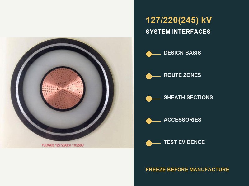
Réponse courte: Traiter un 220 Spécification du câble souterrain kV en tant que programme d'interface système, pas comme fiche technique du câble. Avant fabrication, connecter le service électrique, zones d'itinéraire, sections de gaine, accessoires, longueurs d'usine, et preuve d'acceptation. Une interface ouverte peut toujours produire des longueurs incorrectes, accessoires incompatibles, une disposition de liaison déséquilibrée, ou une preuve qui ne couvre pas le système fourni.
CEI 62067:2022 est la base internationale de contrôle des produits et des tests pour les systèmes de câbles extrudés unipolaires ci-dessus 150 kV et jusqu'à 500 Tension nominale kV dans les conditions habituelles d'installation fixe. Il ne fournit pas une solution universelle 220 construction kV, intensité admissible, disposition de la gaine, longueur du tambour, ou conception d'itinéraire. Ces décisions proviennent des interfaces du projet.

Le cahier des charges doit définir un système, pas une étiquette de tension
« Câble XLPE 220 kV selon CEI 62067 » est un point de départ, pas une spécification complète. La désignation commune 127/220(245) kV enregistre la tension à la terre, tension nominale du système, et tension maximale du système. Cela ne dit toujours rien sur la charge continue, devoir de faute, matériau conducteur, pertes de route, barrière d'eau, courant de défaut de gaine, méthode de liaison, accessoires, force d'installation, ou les limites des preuves.
CEI 60183 traite la sélection haute tension comme une décision coordonnée impliquant la taille du conducteur, niveau d'isolation, construction, accessoires, collage d'écran spécial, et les conditions environnementales. CEI 60287 fournit ensuite des équations de tarage et de perte en régime permanent tout en laissant délibérément de côté les travaux de construction importants, environnement, et les apports convenus en matière de marge de service pour le projet lui-même. C'est pourquoi une capacité de catalogue ne peut pas fermer un 220 Conception d'itinéraire kV.
| Interface à geler | Entrées contrôlées minimales | Qu'est-ce qui peut échouer s'il reste ouvert |
|---|---|---|
| Base de conception électrique. | U0/U(Un), fréquence, mise à la terre, charge continue et cyclique, service d'urgence, courant et durée du défaut, service d'impulsion et de commutation. | Mauvaise base d'isolation, conducteur de zone, devoir de gaine métallique, ou classe accessoire. |
| Modèle d'itinéraire et thermique. | Zones d'installation, données sur le sol/remblai, conduits, air du tunnel, profondeur, espacement, formation, passages à niveau, sources de chaleur adjacentes. | Courant nominal non vérifié ou goulot d'étranglement thermique local. |
| Construction de câbles. | Conducteur, Système XLPE, blocage de l'eau, gaine métallique, gaine extérieure, déclarations incendie ou environnementales. | Construction qui ne correspond pas au tracé, faute, eau, ou conditions d'interface. |
| Système de gaine. | Schéma de liaison, longueurs de sections, mise à la terre, boîtes de liens, fils de liaison, SVL, étude de tension stationnaire et transitoire. | Pertes en circulation, tension de gaine dangereuse, ou une coordination inadéquate de l'isolation. |
| Accessoires. | Type de joint, type de terminaison, équipement connecté, dimensions, matériels, contrôle sur le terrain, interfaces mécaniques et d'étanchéité. | Un accessoire nominalement adapté en dehors de la famille de systèmes qualifiés. |
| Longueurs et logistique. | Route chainage, baies communes, direction de traction, limites du tambour, enveloppe de transport, plan de stockage et de manutention. | Articulations supplémentaires, baies inaccessibles, fûts inadaptés, ou tirages impossibles. |
| Preuve et acceptation. | Édition standard, enveloppe de préqualification et d’essai de type, tests de routine/échantillons, PTI, dossiers de chantier, essai après pose. | Rapports qui ne couvrent pas la conception livrée ou le circuit installé. |
Les données d'itinéraire doivent être entrées en tant que zones contrôlées
Un long circuit souterrain possède rarement un seul environnement thermique. Enterrement direct, conduits enrobés de béton, forage directionnel horizontal, approches du pont, tunnels, baies communes, entrées de sous-station, et les passages à niveau encombrés créent des zones distinctes. Chaque zone a besoin d'un chaînage, géométrie, hypothèses thermiques, méthode d'installation, et statut de conception. La note déterminante peut provenir d'un court segment restrictif plutôt que de l'itinéraire moyen..
Le guide XWA séparé pour contraintes de tracé souterrain explique thermique, tirant, et les effets civils en détail. Pour un 220 spécification kV, résumer ces calculs dans un registre d'interface de route. Enregistrer les limites des zones, apports approuvés, la discipline responsable, la révision des calculs, et toute sensibilité qui affecte encore la sélection du conducteur ou de la construction.
Trois valeurs méritent des enregistrements sources explicites: résistivité thermique du sol ou du remblai, température ambiante ou du sol, et disposition des câbles. Une valeur générique copiée à partir d'une table d'appel d'offres n'est pas équivalente à une preuve d'acheminement. Où le séchage, changement saisonnier, ou une occupation incertaine des conduits est crédible, l'étude de notation doit expliquer le traitement. N'enfouissez pas cette incertitude dans un seul chiffre d'intensité admissible.
La conception de la gaine crée son propre programme de sections
À 220 kV, la gaine métallique fait partie du système électrique et thermique. Il assure le dépistage, assume une obligation de défaut spécifiée, et interagit avec la protection contre l'eau et les accessoires. Sa disposition de liaison influence la tension de la gaine permanente, courant circulant, pertes, note actuelle, protection contre les surtensions, et des conditions de travail sécuritaires.
Collage en un seul point, liaison solide, et la liaison croisée sont des options d'ingénierie, pas de qualité. CIGRE TB 797 souligne que les systèmes de transmission CA au niveau et au-dessus 66 kV nécessitent une conception de liaison de gaine spécifique au projet basée sur le câble, accessoires, conditions de pose, et système connecté. Les liaisons croisées sont courantes sur des 220 Itinéraires kV car des sections mineures équilibrées peuvent réduire la tension induite nette et la perte de circulation, mais ce n'est pas une règle automatique.
| Décision de cautionnement | Des données qui doivent être coordonnées | Enregistrement requis |
|---|---|---|
| Longueurs des sections majeures et mineures. | Route chainage, disposition des phases, positions de baie commune, géométrie du câble. | Nomenclature des sections avec longueurs réelles et calculées. |
| Boîtes de liaison et câbles de liaison. | Emplacement, accessibilité, devoir de chef d'orchestre, niveau d'isolation, connexion à la terre. | Calendrier des équipements et plan de terminaison. |
| Limiteurs de tension de gaine. | Tension stationnaire à fréquence industrielle, étude transitoire, devoir énergétique, coordination de l'isolation. | Hypothèses de l’étude et base de notation retenue. |
| Taille de la gaine métallique. | Courant de défaut, durée, chemins de retour, mode de liaison, limites de matériau et de température. | Calcul des défauts lié au plan de construction. |
| Points de test de mise en service. | Isolement des sections, links, terres, accès à la gaine, interfaces de surveillance. | Tester la correspondance schématique des connexions telles que construites. |
Un changement tardif de baie commune change donc plus que le chaînage civil. Cela peut perturber l’équilibre des sections mineures, longueurs de livraison des câbles, emplacement de la boîte de liens, longueur du fil de liaison, sections de traction, et le plan de test. Renvoyez la modification via le registre d'interface avant de libérer la fabrication du tambour.
Les longueurs de fabrication sont un résultat d'ingénierie
Déduire la longueur de livraison en usine à partir du chaînage des itinéraires et de l’analyse de l’installation, non seulement grâce à la capacité maximale du tambour. Un programme de longueur utile aligne quatre couches: positions de baie commune accessibles, tirages réalisables, sections de liaison équilibrées, et fûts transportables. Il comprend également les indemnités de départ, indemnités de préparation conjointe, tolérances d'itinéraire, exigences en matière d'échantillon, et la politique approuvée pour les longueurs de rechange.
Les joints inutiles ajoutent des interfaces accessoires et des travaux d'installation. Des sections trop longues peuvent dépasser la masse du tambour, enveloppe de transport, tirer la tension, pression sur les flancs, ou capacité de manutention sur site. Le calendrier optimal n’est donc pas « le moins de joints » isolément. Il s'agit de l'arrangement le moins risqué qui satisfait aux exigences électriques., civil, installation, logistique, et contraintes de maintenance réunies.
La version de fabrication doit identifier chaque phase et chaque tambour, chaînage de début et de fin, direction de traction, destination conjointe ou résiliation, longueur de section calculée, longueur commandée, dimensions et masse du tambour, et section de liaison correspondante. Les marques de fûts et les documents d'emballage doivent utiliser les mêmes identifiants que les dessins et les enregistrements du site..
Les accessoires doivent appartenir à la famille de systèmes proposée
N'acceptez pas un 220 Joint ou terminaison kV uniquement parce que la tension indiquée sur la plaque signalétique correspond à celle du câble.. Le diamètre de l'isolation du câble, géométrie de l'écran, connexion du conducteur, interfaces matérielles, et le contrôle du champ électrique comptent. Dilatation thermique, scellage, charges mécaniques, et les équipements connectés affectent également l'interface.
CIGRE TB 968 décrit les interfaces câble-accessoires comme étant des équipements électriques critiques., thermique, matériel, et limites thermomécaniques. Préparation des surfaces, pression d'interface, lubrifiant, contrôle de la contamination, et la compatibilité des matériaux peut affecter les performances. La fiche technique des accessoires doit donc faire référence à la construction exacte du câble et à la plage de tolérance dimensionnelle., pas un générique 220 étiquette famille kV.
Les interfaces de terminaison ont également besoin de la base de l'équipement connecté: terminaison d'air extérieur, Interface SIG, ou branchement transformateur; conditions de pollution et d'altitude; chargement mécanique; espacement des phases; arrangement de soutien; limite de fluide ou de gaz, le cas échéant; et matériel de terminal. Les baies communes ont besoin d'un espace de travail, contrôle environnemental, mise à la terre, soutien, et une procédure d'installation contrôlée.
Carte CEI 62067 preuve de la conception fournie
CEI 62067:2022 spécifie les exigences et les tests pour le système de câbles, câbles, et accessoires dans son champ d'application. Examinez chaque couche de preuves par objectif. Un rapport de préqualification aborde le comportement thermoélectrique à long terme pour une famille de systèmes définie. Les preuves des tests de type portent sur une conception définie. Des tests de routine et des échantillons portent sur les produits manufacturés. Les enregistrements du site et les tests après installation concernent le circuit assemblé. Un document ne peut pas remplacer tous les autres calques.
| Couche de preuves | Réponse à la question | Vérification des interfaces |
|---|---|---|
| Préqualification. | La famille de systèmes a-t-elle obtenu la qualification de longue durée requise? | Comparer le conducteur, système d'isolation, accessoires, dimensions, matériels, classe de tension, et extensions autorisées. |
| Essais de types. | La conception définie des câbles et accessoires a-t-elle réussi les tests de conception applicables? | Confirmer que les combinaisons de raccordement et de résiliation proposées sont représentées. |
| Tests de routine. | Chaque longueur ou accessoire fabriqué requis a-t-il passé avec succès les contrôles de production? | Rapports de traçage au tambour, phase, identité de série accessoire, et révision des dessins. |
| Exemples de tests. | Les caractéristiques de production sélectionnées répondent-elles aux exigences spécifiées? | Définir la fréquence d'échantillonnage, points témoins, acceptation, et gestion des non-conformités. |
| Dossiers d'installation. | Était le transport, tirant, préparation, jointoiement, et fin des travaux maîtrisés? | Lier le personnel, environnement, mesures, matériels, photographies, et feuilles de contrôle. |
| Tests après installation. | Le circuit assemblé répond-il à la base de mise en service approuvée? | Capacité de correspondance avec la source, longueur de l'itinéraire, accessoires, tester les connexions, méthode, et critères d'acceptation. |
CIGRE TB 841 passe en revue les sources de tests modernes après pose et leurs limites pour les systèmes HT et THT. Accepter la méthode, tension, durée, fréquence source, ajouts de diagnostic, et tester les connexions dans le calendrier de tests du projet. Ne les improvisez pas après avoir assemblé le circuit.
Sept points d'arrêt évitent des modifications tardives et coûteuses
- Maintien de référence: geler U0/U(Un), mise à la terre, cas de charge, devoir de faute, coordination de l'isolation, et éditions dirigeantes.
- Maintien du modèle d'itinéraire: approuver le chaînage, entrées de zones, modèle de notation, calculs d'installation, et sensibilités non résolues.
- Maintien de la conception du système: approuver la construction du câble, conducteur, dimensions, gaine métallique, barrière d'eau, et déclarations environnementales.
- Maintien de l'interface accessoire: approuver les joints, résiliations, enveloppes dimensionnelles, équipement connecté, et cartographie des qualifications.
- Tenue de liaison: approuver le calendrier des sections, boîtes de liens, mise à la terre, SVL, coordination de l'isolation, et tester l'accès.
- Maintien de la longueur et du tambour: approuver les longueurs de livraison, direction de traction, baies communes, détails du tambour, tolérances d'itinéraire, et identifiants.
- Plan qualité retenu: approuver l'ITP, modèles de rapport, traçabilité, points témoins, processus de non-conformité, et méthode de mise en service.
Ces points d'arrêt doivent utiliser des révisions contrôlées et des propriétaires nommés. Les CIGRÉ 2026 Les travaux d'AQ/CQ sur le cycle de vie identifient la gestion des interfaces comme un risque central, car les déficiences dans les premières phases du projet peuvent se propager à la fabrication., transport, installation, et fonctionnement. Une fiche technique signée sans interfaces fermées n'est donc pas une version de fabrication fiable.
Un pratique 220 Registre d'interface kV
Le registre peut rester compact si chaque ligne comporte cinq champs: exigence, entrée vérifiée, référence à la preuve, propriétaire responsable, et statut. Les éléments non soldés doivent afficher la date de la décision et les documents en aval qu'ils bloquent. Le registre le plus utile n’est pas le plus long; c'est celui qui rend visibles les dépendances.
- Tension et système: 127/220(245) désignation kV, Fréquence CA, mise à la terre, base de surtension, cas de charge et de panne.
- Itinéraire: chaînage, dessins de zones, valeurs thermiques, formation, espacement, profondeur, méthode civile, contrôles de traction et de flexion.
- Construction: conducteur, système d'isolation, gaine métallique, protection de l'eau, gaine extérieure, dimensions et tolérances.
- Accessoires: conceptions exactes de joints et de terminaisons, fenêtres dimensionnelles de câble, équipement connecté, conditions de pose.
- Collage: sections majeures/mineures, boîtes de liens, conduit, terres, SVL, calculs de tension de gaine et de service de défaut.
- Fabrication: planning phase/tambour, longueurs commandées, échantillons, marquages, points de contrôle, limites de transport et de stockage.
- Preuve: matrice de qualification, rapports de production, dossier de traçabilité, dossiers d'installation, tel que construit, rapport de mise en service.
Questions courantes sur 220 Spécifications kV souterraines
La CEI 62067 définir la note actuelle d'un 220 câble kV?
Non. CEI 62067 définit les tests et les exigences dans son domaine d'application. La puissance nominale dépend de la construction réelle, pertes, géométrie d'installation, environnement thermique, arrangement de liaison, et service d'exploitation. CEI 60287 fournit des méthodes de calcul, pas une seule valeur catalogue universelle.
La liaison croisée est-elle obligatoire pour chaque 220 itinéraire kV?
Non. Les ingénieurs doivent concevoir le système de gaine du circuit. Les liaisons croisées conviennent souvent aux itinéraires plus longs. Les arrangements à point unique ou solides peuvent s'adapter à des longueurs et à des conditions de section particulières. La décision nécessite une tension induite, perte, faute, transitoire, mise à la terre, et analyse de maintenance.
Les positions des baies communes peuvent-elles rester ouvertes jusqu'à la fabrication du câble?
Cela crée un risque majeur. Les baies communes contrôlent les longueurs de livraison, sections de traction, équilibre de la section de liaison, emplacements des boîtes de liens, quantités d'accessoires, et accès au site. Les positions provisoires doivent bloquer la libération finale du tambour à moins qu'il n'existe une méthode de tolérance et de changement approuvée..
Un rapport de préqualification prouve-t-il le circuit livré?
Il prend en charge une famille de systèmes qualifiés définis. Mappez la construction et les accessoires proposés à cette famille et ses règles d'extension. Production, installation, et les preuves de mise en service restent nécessaires séparément.
Ce qui doit figurer dans la soumission technique finale?
La soumission doit aligner le calendrier du câble, dessins de construction, interfaces accessoires, étude de liaison, rapport de notation, calendrier de livraison, matrice de qualification, PTI, rapports de production, dossiers d'installation, dessins d'exécution, et rapport de test après installation sous un index contrôlé par révision.
Conclusion d'ingénierie
Un fiable 220 La spécification du câble souterrain kV est un document de contrôle d'interface. CEI 62067 établit la base de test du système. La performance du projet dépend également des liens entre le service électrique, zones d'itinéraire, construction, gaine métallique, accessoires, longueurs, installation, et des preuves. Libérez la fabrication uniquement lorsque chaque tambour et accessoire dispose d'un chemin traçable depuis l'entrée de conception jusqu'à la position d'acheminement.. Le même chemin doit relier l’enveloppe de qualification au dossier de mise en service.
Le XWA concerné 127/220(245) Gamme de produits kV fournit une classe de tension et un contexte de construction, tandis que le plus large gamme de câbles haute tension le place dans le 66-500 Gamme du système kV. Pour des conseils techniques neutres sur la conception de gaines spécifiques à un projet, voir le Présentation technique du CIGRE.
Soumettez le 220 Calendrier des interfaces kV
Pour une revue d'ingénierie, fournir U0/U(Un), fréquence et mise à la terre, cas de charges continues et d'urgence, courant et durée du défaut, chaînage routier et zones thermiques, formation et méthode civile, notion de liaison, interfaces de baie commune et de terminaison, édition CEI requise, exigences de qualification et d’essai, quantités de livraison, et destination. Puissance XWA & Le câble peut aligner la construction proposée, données d'interface accessoire, longueurs de fabrication, et calendrier des preuves avec la base du système approuvé. La confirmation finale de la capacité fait suite à la fermeture des interfaces techniques.