
N2XS(F)2Y cable is a screened single-core copper MV power cable with XLPE insulation, a copper wire screen, longitudinal water-blocking components and a PE outer sheath for fixed distribution.
The copper conductor carries load current; the surrounding screen performs a separate electrical duty. Industrial feeders, substation circuits and underground networks use this construction where the voltage, bonding arrangement and route conditions match the cable-system design.
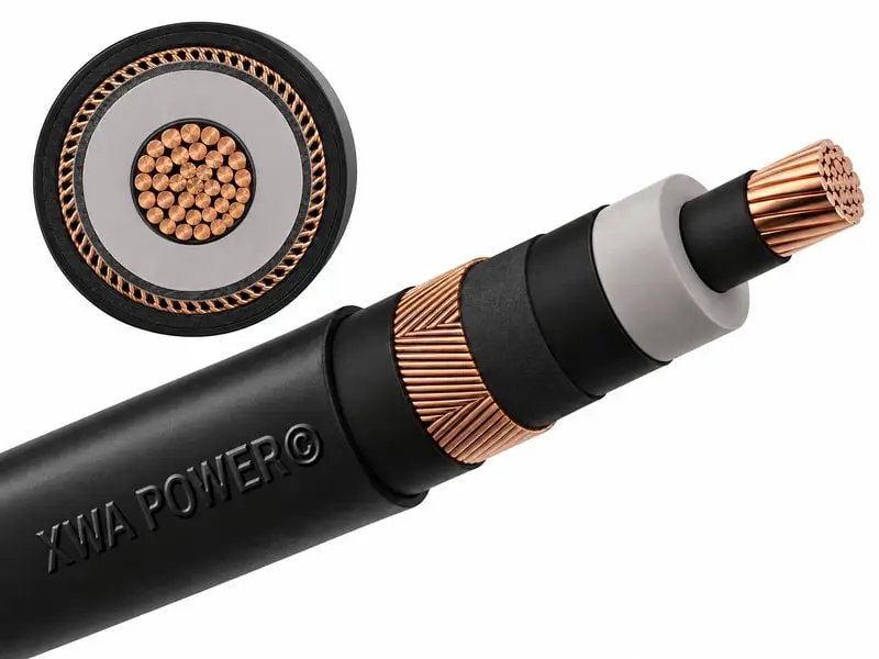
CONSTRUCTION
- Conductor
- Stranded copper
- Insulation
- XLPE between semiconductive conductor and insulation screens
- Screen region
- Copper wires and tape; longitudinal water-blocking components
- Outer sheath
- Black PE; no armour in the reference construction
CHARACTERISTICS
- Reference voltage
- 12/20 (24) kV
- Core configuration
- Single-core; separate conductor and screen areas
- Thermal reference
- 90°C maximum operating conductor temperature in the source design
- Standard context
- HD 620 / DIN VDE 0276-620; agreed project requirements
N2XS(F)2Y for Fixed Power Distribution
Voltage, conductor/screen size and route conditions define the project configuration.
N2XS(F)2Y Cable Technical Data
Recommended Reference Data: published values for preliminary comparison. Final supply dimensions, ratings and size range follow the agreed XWA datasheet.
| Cable size (mm²) | DC resistance 20°C (Ω/km) | Insulation (mm) | Approx. OD (mm) | Approx. mass (kg/km) | Air (A) | Ground (A) |
|---|---|---|---|---|---|---|
| 1 x 95/16 | 0.193 | 5.5 | 32 | 1580 | 361 | 323 |
| 1 x 150/25 | 0.124 | 5.5 | 35 | 2212 | 470 | 409 |
| 1 x 240/25 | 0.075 | 5.5 | 39 | 3181 | 634 | 532 |
| 1 x 300/25 | 0.060 | 5.5 | 42 | 3851 | 724 | 599 |
| 1 x 400/35 | 0.047 | 5.5 | 44 | 4795 | 829 | 671 |
| 1 x 500/35 | 0.037 | 5.5 | 47 | 5873 | 953 | 754 |
Copper single-core N2XS(F)2Y, 12/20 kV, copper wire screen and PE sheath. The listed dimensions, mass and current ratings apply to this reference construction and the installation conditions below.
Ampacity basis: one circuit in touching trefoil, screens solidly bonded; air 30°C without direct sun; ground 20°C at 0.7 m depth. Source assumptions include 1.0 K·m/W wet soil and 2.5 K·m/W dry soil, with no additional heat sources. Reference conductor limit: 90°C.
Copper conductor, metallic screen and the (F) designation
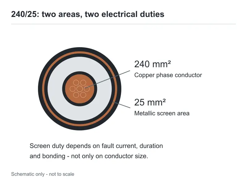
In a reference 1×240/25 construction, 240 mm² belongs to the phase conductor and 25 mm² to the metallic screen. Screen fault-current duty, protection clearing time and accessory connections are separate from continuous conductor ampacity.
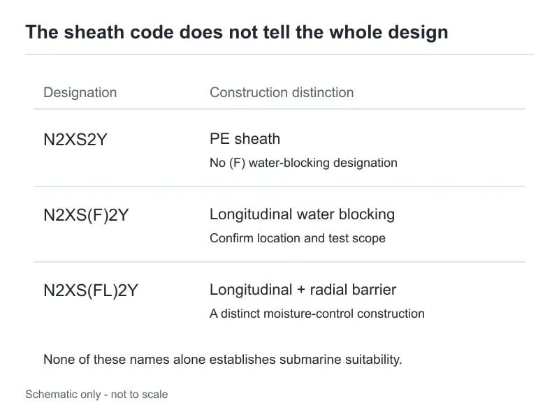
The (F) construction restricts water travel along the specified cable region. N2XS(FL)2Y adds a laminated metallic barrier beneath the PE sheath to reduce radial moisture ingress.
Applications and Installation Conditions
Typical routes include industrial power intake, substation feeders and underground distribution. Mechanical protection, fire requirements, moisture exposure and accessory interfaces are specified for the installation.
The test schedule covers conductor resistance, insulation, sheath integrity and the specified longitudinal water-blocking performance. Screen connections and accessory interfaces complete the system design. The IEC publication scope describes the fixed-installation framework.
N2XS(F)2Y and Related Constructions
| Model | Main difference |
|---|---|
| N2XS2Y cable | Copper conductor, XLPE insulation and PE sheath; longitudinal water blocking is not specified by the N2XS2Y designation. |
| N2XSY cable | Copper screened MV cable with PVC outer sheath. |
| N2XS(FL)2Y | Combines longitudinal water blocking with a laminated metallic barrier beneath the PE sheath for radial moisture protection. |
N2XS(F)2Y Cable FAQs
Are N2XS(F)2Y and N2XS2Y interchangeable?
The (F) version adds longitudinal water-blocking components to the screened cable construction. The project moisture requirements determine whether this feature is needed.
What does 1×240/25 identify?
It identifies one 240 mm² phase conductor and a separately specified 25 mm² metallic screen.
Can the displayed ampacity be used for ducts?
The displayed values use the stated trefoil, bonding and thermal conditions. Ducts and grouped circuits require a calculation for their own surrounding materials and installation geometry.