
XWA POWER & CABLE | STEEL TAPE ARMOURED POWER CABLE
XLPE/STA/PVC Cable combines XLPE-insulated conductors, steel tape armour and a PVC outer sheath for fixed power distribution. The armour forms a metal covering around the core assembly where the route calls for integral mechanical protection.
For fixed feeders, we recommend matching the armour to the route rather than treating a heavier cable as an automatic upgrade. Steel tape protection, pulling arrangements and termination space need to work together. This family includes unscreened LV and screened MV designs, each with its own electrical construction.
Discuss an STA cable project- Mechanical layer
- Steel tapes
- Electrical insulation
- XLPE
- Product family
- LV and screened MV
XLPE/STA/PVC cable product views
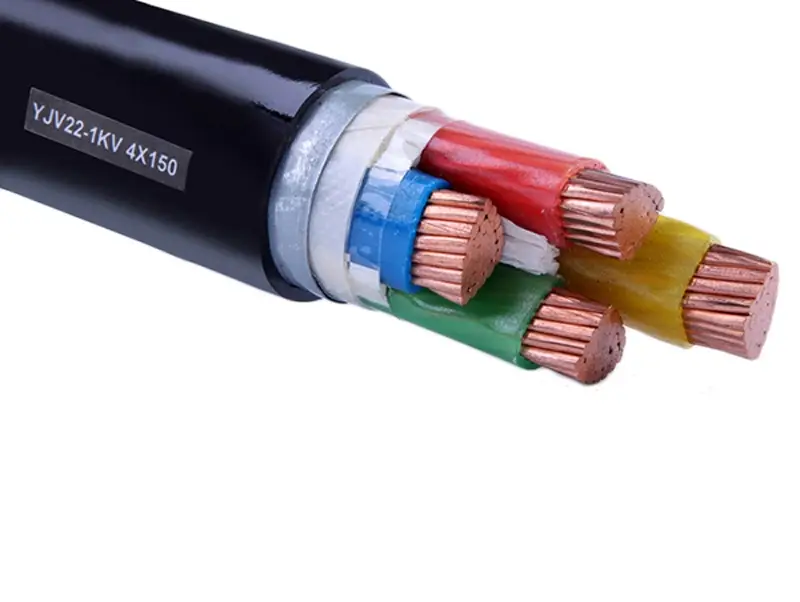
Four-core cable sample
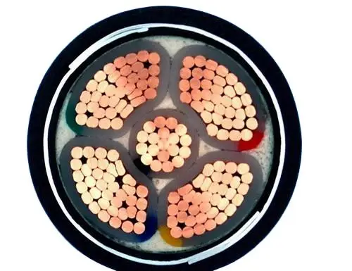
Five-core cross-section
XLPE/STA/PVC construction from core to outer sheath
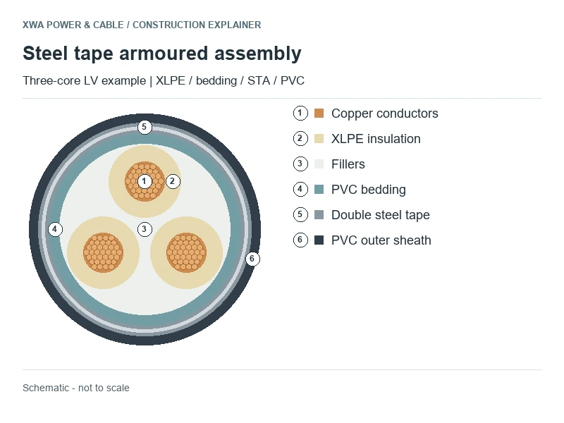
In the LV example, stranded copper cores sit within XLPE insulation. Fillers shape the laid-up assembly, PVC bedding separates it from the metal armour, and a PVC sheath covers the tapes. The fuller layer description is CU/XLPE/PVC/STA/PVC.
Double steel tape armour uses two tape layers around the bedding. Tape thickness, width and application geometry affect armour coverage and finished cable diameter.
Copper and aluminium phase conductors are different configurations of this family. The CU or AL prefix identifies the power conductor, while STA identifies steel in the armour. Core count and any reduced neutral or protective conductor must also be defined in the cable schedule.
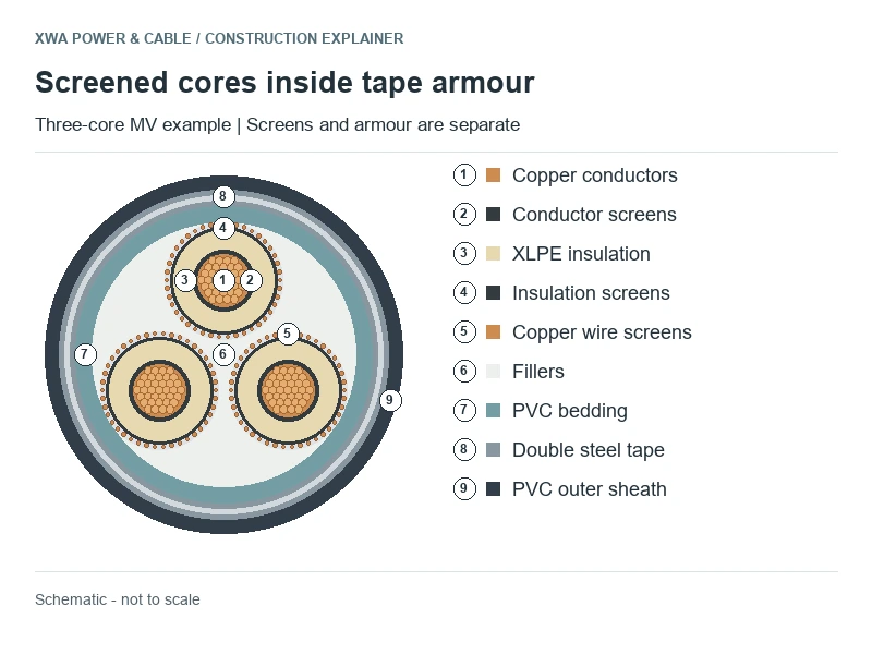
Screened MV cores under common tape armour
Screened MV constructions use conductor and insulation semiconductive layers to control the electric field, plus a copper tape or copper wire screen for the specified electrical duty.
The three screened cores sit within the common bedding and steel tape armour. The illustration shows copper wire screens, matching the screen type used in the reference table.
Metallic screen section, voltage, core arrangement and accessory dimensions are specified together in the construction drawing.
Explore the related medium-voltage power cable range for voltage-specific constructions.
12/20 kV three-core STA reference dimensions
Recommended Reference Data: copper-conductor, copper-wire-screened, three-core XLPE/PVC/STA/PVC, rated 12/20 (24) kV. Screen entries identify the metallic-screen section for the stated design.
| Cores & phase section (mm²) | Max. DC resistance at 20°C (Ω/km) | XLPE thickness (mm) | Screen section (mm²) | Approx. OD (mm) | Approx. mass (kg/km) |
|---|---|---|---|---|---|
| 3 × 95 | 0.193 | 5.5 | 16 | 72 | 7200 |
| 3 × 150 | 0.124 | 5.5 | 25 | 80 | 9300 |
| 3 × 185 | 0.0991 | 5.5 | 25 | 83 | 10700 |
| 3 × 240 | 0.0754 | 5.5 | 25 | 90 | 13800 |
| 3 × 300 | 0.0601 | 5.5 | 25 | 95 | 16000 |
| 3 × 400 | 0.0470 | 5.5 | 35 | 98 | 18500 |
These published reference dimensions support preliminary planning; final supply dimensions follow the agreed XWA datasheet. Copper-tape screens, aluminium conductors and other voltages have their own construction data.
For the 3 × 240 mm² reference, approximate diameter is 90 mm and cable mass is 13,800 kg/km. A 100 m length therefore contains about 1,380 kg of cable. Packing weight and permitted pulling load are calculated separately.
Current rating depends on installation, ambient conditions, soil thermal properties, grouping and screen/armour losses. The table covers a screened MV construction; LV versions use separate dimensional data.
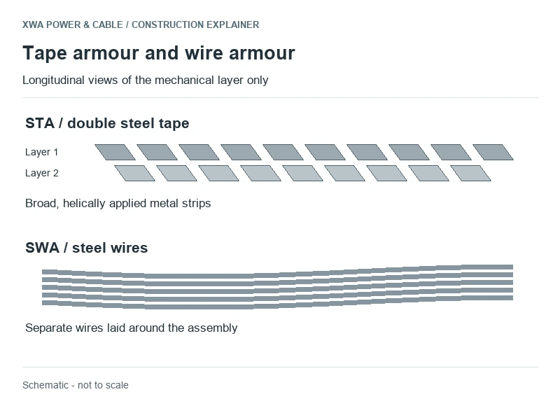
STA and SWA have different mechanical arrangements
STA uses broad steel strips; SWA uses individual steel wires. The different geometry affects mechanical behaviour, finished dimensions and termination requirements.
| Construction decision | STA consequence | Related design consideration |
|---|---|---|
| Integral mechanical protection | Steel tapes surround the bedded multicore assembly. | Compression, impact and other required performance must be assessed for the complete design; the abbreviation gives no test rating. |
| Pulling and vertical support | Tape armour must not be treated as a lifting member. | The permissible load depends on cable construction, pulling method, attachment and support arrangement. |
| Armour connection | The termination must make the specified connection to the tape layers. | A gland or bonding arrangement designed only for round wires must not be assumed compatible. |
| Cable space and handling | OD and mass depend on the entire layer stack. | Tape armour is not automatically lighter or smaller than every SWA design. Compare matching voltage, cores and conductor sections. |
The XLPE/SWA/PVC structure is the wire-armoured counterpart. Route conditions and termination requirements determine the appropriate armour arrangement.
Industrial, underground and substation applications
Industrial distribution
Multicore tape-armoured feeders can connect fixed distribution equipment where the cable specification requires mechanical protection. Fault duty, voltage drop and entry space remain circuit-design inputs.
Duct and buried feeders
Tape armour provides mechanical protection on suitable duct and buried routes. Ground pressure, duct friction, soil conditions and moisture exposure inform the complete installation design.
Substation connections
Screened MV tape-armoured feeders can connect transformers, switchgear and distribution equipment on fixed power routes.
Steel armour is commonly applied around multicore AC assemblies. Individual single-core AC phases generally use non-magnetic armour to control magnetic losses and heating.
For chemically exposed or wet routes, the sheath and moisture-protection system are specified for the environment. Reeling, suspended and subsea duties require purpose-designed cables.
Installation, bending and bonding
Pulling heads, grips, bend guides and supports apply loads to different parts of the cable. The pulling method and approved cable limits determine the installation plan.
The approved instructions must state the permitted bending radius, pulling load and installation temperature. Bending space must use the cable’s actual overall diameter rather than its conductor section. See cable bending radius and pulling tension for the route-planning relationship.
Armour earthing and screen bonding are coordinated with the circuit fault duty. Where armour serves as a protective conductor, continuity and fault-current capacity are checked for the complete connection arrangement.
Electrical, sheath and fire requirements
IEC 60502-1 covers the relevant LV power-cable range, IEC 60502-2 the specified MV range, and IEC 60228 conductor requirements. The voltage and construction determine the applicable test schedule.
The official fixed-installation scope describes the IEC 60502-2 coverage for cables used in fixed distribution installations.
The PVC compound determines the specified sheath properties. Routes requiring low smoke, halogen-free materials, circuit integrity, UV resistance or chemical resistance need the corresponding material system and tests.
Related structures and configuration choices
| Structure | What changes | Where the distinction matters |
|---|---|---|
| CU/XLPE/PVC/STA/PVC | Copper phase conductors and tape armour, with PVC bedding and sheath. | An LV construction can be unscreened; MV requires the relevant electrical screens. |
| AL/XLPE/…/STA/PVC | Aluminium phase conductors within a specified STA construction. | Terminations, section, resistance and finished dimensions change; copper reference rows do not apply. |
| XLPE/SWA/PVC Cable | Steel wires instead of steel tapes. | Mechanical behaviour, gland arrangement and the construction datasheet must match the specified armour. |
| N2XY Cable | An unarmoured copper/XLPE/PVC model. | External route protection or a different construction replaces the integral armour function. |
Explore Cable Structures for other insulation, screening, armour and sheath combinations.
XWA manufacturing and inspection
XWA Power & Cable manufactures power cables for utility, industrial and infrastructure projects. Our factory operations include conductor processing, insulation extrusion, screening, cabling, armouring and sheathing.
Cable orders can be manufactured to customer drawings, cable schedules and agreed technical specifications. Production begins after approval of the technical datasheet; the inspection plan defines the applicable tests and reporting requirements.
Factory visits, video inspections and third-party inspections can be arranged with XWA. Explore our cable factory and quality-control process.
Questions about the STA construction
Does STA mean two steel tapes?
STA means steel tape armour. The examples on this page use double steel tape; tape count, thickness, width and application arrangement belong to the specified construction.
Does XLPE/STA/PVC identify the voltage rating?
XLPE/STA/PVC identifies the insulation, armour and outer-sheath materials. Rated voltage and the electrical screens define the LV or MV version.
Can steel tape armour carry the installation pulling load?
The permitted pulling load depends on the cable design, attachment method and route. Use the approved pulling arrangement; steel tape is not a lifting point.
Why are the MV copper screen and steel armour separate?
The copper screen performs its specified electrical duty around the insulated cores. The steel tape armour provides mechanical protection outside the bedded assembly.
Are 3-core and 4-core STA cables covered by the same dimensions?
Three-core and four-core constructions have different assembled dimensions. The table covers screened three-core MV cable; four-core LV designs use their own datasheets.
Discuss an XLPE/STA/PVC cable requirement
Contact XWA for an XLPE/STA/PVC quotation. Email your cable schedule or tell us the voltage, core arrangement, conductor size and project length.