
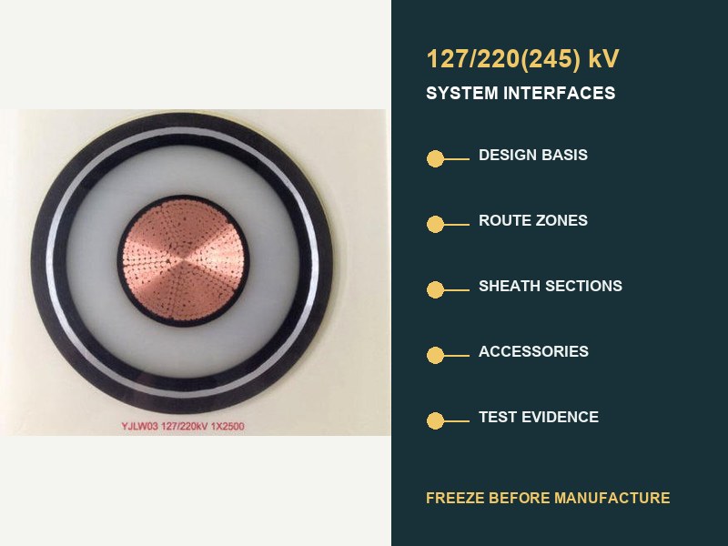
Kratak odgovor: Treat a 220 kV underground cable specification as a system interface schedule, not as a cable datasheet. Before manufacture, connect the electrical duty, zone rute, sekcije omotača, pribor, factory lengths, and acceptance evidence. An open interface can still produce wrong lengths, incompatible accessories, an unbalanced bonding layout, or evidence that does not cover the supplied system.
IEC 62067:2022 is the controlling international product-and-test basis for extruded single-core cable systems above 150 kV i do 500 kV rated voltage under usual fixed-installation conditions. It does not provide one universal 220 kV construction, ampacity, sheath arrangement, dužina bubnja, or route design. Those decisions come from the project interfaces.

The specification must define a system, not a voltage label
“220 kV XLPE cable to IEC 62067” is a starting point, not a complete specification. The common designation 127/220(245) kV records voltage to earth, rated system voltage, and maximum system voltage. It still says nothing about continuous load, greška, materijal provodnika, route losses, vodena barijera, sheath fault current, metoda vezivanja, pribor, installation force, or evidence boundaries.
IEC 60183 treats high-voltage selection as a coordinated decision involving conductor size, nivo izolacije, izgradnja, pribor, special screen bonding, and environmental conditions. IEC 60287 then provides steady-state rating and loss equations while deliberately leaving important construction, okruženje, and agreed service-margin inputs to the actual project. This is why a catalogue ampacity cannot close a 220 kV route design.
| Interface to freeze | Minimum controlled inputs | What can fail if it remains open |
|---|---|---|
| Electrical design basis. | U0/U(Jedan), frekvencija, uzemljenje, continuous and cyclic load, emergency duty, fault current and duration, impulse and switching duty. | Wrong insulation basis, provodnik područja, metallic sheath duty, or accessory class. |
| Route and thermal model. | Installation zones, soil/backfill data, kanali, tunnel air, dubina, razmak, formiranje, prelaze, adjacent heat sources. | Unverified current rating or a local thermal bottleneck. |
| Izgradnja kablova. | Dirigent, XLPE system, blokiranje vode, metalni omotač, vanjski omotač, fire or environmental declarations. | Construction that does not match route, greška, vode, or interface conditions. |
| Sheath system. | Bonding schematic, dužine sekcija, uzemljenje, link boxes, vezivanje vodi, SVLs, standing and transient voltage study. | Circulating losses, unsafe sheath voltage, or inadequate insulation coordination. |
| Pribor. | Joint type, termination type, povezana oprema, dimenzije, materijala, field control, mechanical and sealing interfaces. | A nominally matched accessory outside the qualified system family. |
| Lengths and logistics. | Route chainage, spojnice, smjer povlačenja, granice bubnja, transport envelope, storage and handling plan. | Extra joints, inaccessible bays, unsuitable drums, or impossible pulls. |
| Evidence and acceptance. | Standard edition, prequalification and type-test envelope, routine/sample tests, ITP, site records, after-laying test. | Reports that do not cover the delivered design or installed circuit. |
Route data should enter as controlled zones
A long underground circuit rarely has one thermal environment. Direktno sahranjivanje, concrete-encased ducts, horizontal directional drilling, bridge approaches, tuneli, spojnice, substation entries, and congested crossings create distinct zones. Each zone needs chainage, geometrija, thermal assumptions, način instalacije, and design status. The governing rating may come from a short restrictive segment rather than the average route.
The separate XWA guide to ograničenja podzemnih ruta explains thermal, povlačenje, and civil effects in detail. Za a 220 kV specification, summarize those calculations in a route-interface register. Record zone boundaries, approved inputs, the responsible discipline, the calculation revision, and any sensitivity that still affects conductor or construction selection.
Three values deserve explicit source records: soil or backfill thermal resistivity, ambient or soil temperature, and cable arrangement. A generic value copied from a tender table is not equivalent to route evidence. Where drying, seasonal change, or uncertain duct occupancy is credible, the rating study should explain the treatment. Do not bury that uncertainty inside one ampacity number.
Sheath design creates its own section schedule
At 220 kV, the metallic sheath is part of the electrical and thermal system. It provides screening, carries specified fault duty, and interacts with water protection and accessories. Its bonding arrangement influences standing sheath voltage, cirkulirajuća struja, gubitke, trenutni rejting, overvoltage protection, and safe work conditions.
Vezivanje u jednoj tački, solid bonding, and cross-bonding are engineering options, not quality grades. CIGRE TB 797 emphasizes that AC transmission systems at and above 66 kV require a project-specific sheath bonding design based on the cable, pribor, uslovi ugradnje, and connected system. Cross-bonding is common on longer 220 kV routes because balanced minor sections can reduce net induced voltage and circulating loss, but it is not an automatic rule.
| Bonding decision | Data that must be coordinated | Required record |
|---|---|---|
| Major and minor section lengths. | Route chainage, fazni raspored, joint-bay positions, geometrija kabla. | Section schedule with actual and calculated lengths. |
| Link boxes and bonding leads. | Location, accessibility, conductor duty, nivo izolacije, earth connection. | Equipment schedule and termination drawing. |
| Sheath voltage limiters. | Power-frequency standing voltage, transient study, energetska dužnost, koordinacija izolacije. | Study assumptions and selected rating basis. |
| Metallic sheath size. | Struja kvara, trajanje, return paths, bonding mode, material and temperature limits. | Fault-duty calculation linked to construction drawing. |
| Commissioning test points. | Section isolation, links, zemlje, oversheath access, monitoring interfaces. | Test schematic matching as-built connections. |
A late change to a joint bay therefore changes more than civil chainage. It may disturb minor-section balance, cable delivery lengths, link-box lokacija, dužina spojnog kabla, pulling sections, and the test plan. Return the change through the interface register before releasing drum manufacture.
Manufacturing lengths are an engineering output
Derive factory delivery length from route chainage and installation analysis, not only from maximum drum capacity. A useful length schedule aligns four layers: accessible joint-bay positions, feasible pulls, balanced bonding sections, and transportable drums. It also includes termination allowances, joint preparation allowances, route tolerances, sample requirements, and the approved policy for spare length.
Unnecessary joints add accessory interfaces and installation work. Excessively long sections can exceed drum mass, transport envelope, povlačenjem napetosti, bočni pritisak, or site handling capability. The optimum schedule is therefore not “fewest joints” in isolation. It is the lowest-risk arrangement that satisfies electrical, civil, instalacija, logistika, and maintenance constraints together.
The manufacturing release should identify each phase and drum, start and end chainage, smjer povlačenja, destination joint or termination, calculated section length, ordered length, drum dimensions and mass, and corresponding bonding section. Drum marks and packing documents should use the same identifiers as drawings and site records.
Accessories must belong to the offered system family
Do not accept a 220 kV joint or termination only because its nameplate voltage matches the cable. The cable insulation diameter, screen geometry, priključak provodnika, material interfaces, and electric-field control all matter. Thermal expansion, zaptivanje, mechanical loads, and connected equipment also affect the interface.
CIGRE TB 968 describes cable-accessory interfaces as critical electrical, termalni, materijal, and thermomechanical boundaries. Surface preparation, interface pressure, lubrikant, contamination control, and material compatibility can affect performance. Tehnički list pribora stoga treba da upućuje na tačnu konstrukciju kabla i raspon tolerancija dimenzija, nije generički 220 kV porodična oznaka.
Interfejsima za završetak takođe je potrebna osnova povezane opreme: zatvaranje vanjskog zraka, GIS interfejs, ili priključka na transformator; zagađenje i visinske uslove; mehaničko opterećenje; fazni razmak; aranžman podrške; granica fluida ili gasa gde je to primenjivo; i terminalni hardver. Spojnicama je potreban radni prostor, kontrola životne sredine, uzemljenje, podrška, i kontrolirani postupak instalacije.
Karta IEC 62067 dokaz za isporučeni dizajn
IEC 62067:2022 specificira zahtjeve i testove za kablovski sistem, kablovi, i pribor u svom obimu. Pregledajte svaki sloj dokaza prema svrsi. Izvještaj o pretkvalifikaciji bavi se dugoročnim termo-električnim ponašanjem za definiranu porodicu sistema. Dokaz o tipskom testu se odnosi na definisani dizajn. Rutinski testovi i testovi uzoraka odnose se na proizvedenu proizvodnju. Site records and after-installation tests address the assembled circuit. One document cannot replace all other layers.
| Evidence layer | Question answered | Interface check |
|---|---|---|
| Prequalification. | Has the system family completed the required long-duration qualification? | Compare conductor, izolacioni sistem, pribor, dimenzije, materijala, klasa napona, and permitted extensions. |
| Testovi tipa. | Has the defined cable-and-accessory design passed the applicable design tests? | Confirm offered joint and termination combinations are represented. |
| Routine tests. | Has each required manufactured length or accessory passed production checks? | Trace reports to drum, phase, accessory serial identity, i revizija crteža. |
| Sample tests. | Do selected production characteristics meet specified requirements? | Define sampling frequency, tačke svedoka, acceptance, and nonconformance handling. |
| Installation records. | Was transport, povlačenje, preparation, spajanje, and termination work controlled? | Link personnel, okruženje, mjerenja, materijala, fotografije, i kontrolne listove. |
| Testovi nakon ugradnje. | Da li sklopljeno kolo ispunjava odobrenu osnovu za puštanje u rad? | Mogućnost podudaranja izvora, dužina rute, pribor, probne veze, metoda, i kriterijume prihvatanja. |
CIGRE TB 841 razmatra moderne izvore ispitivanja nakon polaganja i njihova ograničenja za HV i EHV sisteme. Slažem se sa metodom, napon, trajanje, frekvencija izvora, dijagnostički dodaci, i ispitne veze u rasporedu testiranja projekta. Nemojte ih improvizirati nakon sklapanja kola.
Sedam tačaka zadržavanja sprečavaju skupe kasne promene
- Držanje na bazi dizajna: zamrznuti U0/U(Jedan), uzemljenje, slučajevi opterećenja, greška, koordinacija izolacije, i vladajuća izdanja.
- Zadržavanje modela rute: odobriti stacioniranje, zonski ulazi, model ocjenjivanja, kalkulacije instalacije, i neriješene osjetljivosti.
- Zadržavanje dizajna sistema: odobri konstrukciju kablova, kondukter, dimenzije, metalni omotač, vodena barijera, i ekološke deklaracije.
- Držanje interfejsa za dodatnu opremu: odobri spojeve, prekidi, dimenzionalne koverte, povezana oprema, i mapiranje kvalifikacija.
- Bonding hold: odobri raspored sekcija, link boxes, uzemljenje, SVLs, koordinacija izolacije, i testni pristup.
- Length-and-drum hold: approve delivery lengths, smjer povlačenja, spojnice, drum details, route tolerances, and identifiers.
- Quality-plan hold: approve the ITP, report templates, sljedivost, tačke svedoka, nonconformance process, and commissioning method.
These hold points should use controlled revisions and named owners. CIGRE's 2026 lifecycle QA/QC work identifies interface management as a central risk because deficiencies in early project phases can propagate into manufacturing, transport, instalacija, i operacija. A signed datasheet without closed interfaces is therefore not a reliable manufacturing release.
A practical 220 kV interface register
The register can remain compact if every line has five fields: requirement, verified input, evidence reference, responsible owner, and status. Open items should show the decision date and the downstream documents they block. The most useful register is not the longest one; it is the one that makes dependencies visible.
- Voltage and system: 127/220(245) kV designation, AC frequency, uzemljenje, overvoltage basis, load and fault cases.
- Ruta: chainage, zone drawings, thermal values, formiranje, razmak, dubina, civil method, pull and bending checks.
- Izgradnja: kondukter, izolacioni sistem, metalni omotač, zaštita voda, vanjski omotač, dimensions and tolerances.
- Pribor: exact joint and termination designs, cable dimensional windows, povezana oprema, uslovi ugradnje.
- Vezanje: major/minor sections, link boxes, leads, zemlje, SVLs, sheath-voltage and fault-duty calculations.
- Manufacturing: phase/drum schedule, ordered lengths, samples, markings, inspection points, transport and storage limits.
- Dokaz: qualification matrix, production reports, traceability dossier, installation records, as-builts, commissioning report.
Common questions about 220 kV underground specifications
Da li IEC 62067 define the current rating of a 220 kV kabl?
br. IEC 62067 defines tests and requirements within its scope. Current rating depends on the actual construction, gubitke, installation geometry, termalno okruženje, aranžman vezivanja, i operativne dužnosti. IEC 60287 provides calculation methods, not one universal catalogue value.
Is cross-bonding mandatory for every 220 kV route?
br. Engineers must design the sheath system for the circuit. Cross-bonding often suits longer routes. Single-point or solid arrangements may fit particular section lengths and conditions. The decision requires induced-voltage, gubitak, greška, prolazno, uzemljenje, and maintenance analysis.
Can joint-bay positions remain open until after cable manufacture?
That creates major risk. Joint bays control delivery lengths, pulling sections, bonding-section balance, link-box lokacije, accessory quantities, and site access. Provisional positions should block final drum release unless an approved tolerance and change method exist.
Does a prequalification report prove the delivered circuit?
It supports a defined qualified system family. Map the offered construction and accessories to that family and its extension rules. Production, instalacija, and commissioning evidence remain separately necessary.
Ono što spada u završni tehnički podnesak?
Podnesak treba da uskladi raspored kablovske, građevinski crteži, interfejsi dodatne opreme, studija vezivanja, rejting izvještaj, raspored dužine isporuke, qualification matrix, ITP, production reports, installation records, urađeni crteži, i izvještaj o testiranju nakon instalacije pod jednim indeksom kontroliranim revizijom.
Inženjerski zaključak
Pouzdan 220 Specifikacija kV podzemnog kabla je dokument za kontrolu interfejsa. IEC 62067 uspostavlja osnovu za testiranje sistema. Izvedba projekta također ovisi o vezama između električnih obaveza, zone rute, izgradnja, metalni omotač, pribor, dužine, instalacija, i dokaze. Oslobodite proizvodnju samo kada svaki bubanj i pribor imaju sljedljivu putanju od ulaznog dizajna do pozicije rute. Isti put bi trebao povezati kvalifikacijsku omotnicu sa zapisom o puštanju u rad.
Relevantni XWA 127/220(245) kV asortiman proizvoda pruža naponsku klasu i konstrukcijski kontekst, dok šire portfelj visokonaponskih kablova smješta unutar 66-500 kV sistemski opseg. Za neutralne inženjerske smjernice o dizajnu plašta specifičnog za projekat, vidi CIGRE tehnički pregled.
Pošaljite 220 kV Interfejs Raspored
Za inženjerski pregled, obezbijediti U0/U(Jedan), frekvencija i uzemljenje, slučajevi kontinuiranog i hitnog opterećenja, fault current and duration, stacioniranje trase i termalne zone, formiranje i građanski metod, koncept vezivanja, spojnice za spojeve i terminale, potrebno IEC izdanje, kvalifikacije i zahtjevi za ispitivanje, količine isporuke, i odredište. XWA Power & Kabel može uskladiti predloženu konstrukciju, podaci o dodatnom interfejsu, proizvodne dužine, i raspored evidencije sa odobrenom osnovom sistema. Konačna potvrda sposobnosti slijedi nakon zatvaranja tehničkih interfejsa.