
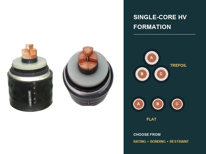
Trefoil is usually the stronger starting point when a single-core HV cable circuit needs compact geometry, lower external magnetic field, and balanced phase spacing. Flat formation becomes attractive when route width permits deliberate spacing, heat dissipation or access benefits from separation, or the civil arrangement cannot accommodate trefoil. Neither arrangement has a universal ampacity advantage.
The correct decision requires one calculation model containing the actual cable, Phasenreihenfolge, Abstand, installation medium, adjacent circuits, metallic-sheath design, Klebemethode, load cycle, Kurzschlussbetrieb, and mechanical restraint. Changing formation on site changes that model; it is not a harmless drawing adjustment.
Start with geometry, not a catalogue rating.
A three-phase circuit carries currents separated in phase. Their magnetic fields interact with each other, with each cable’s metallic sheath, and with nearby conductive structures. Trefoil places the three cable centres at the corners of a compact triangle. Flat formation places them on one line, either touching or at defined centre spacing.
That geometry enters several linked calculations. It changes mutual inductance and sheath-induced voltage. It changes circulating losses under solid bonding. It changes heat flow between phases and the surrounding medium. It also changes short-circuit forces, cleat loading, Streckenbreite, magnetic-field distribution, and access for installation.
IEC 60287-1-1 provides steady-state current-rating equations and loss calculations, während IEC 60287-2-1 addresses thermal resistance. Both require construction and installation inputs. They do not assign one permanent rating to “trefoil” or “flat” without those inputs.

Trefoil compresses the magnetic loop.
In trefoil, each phase has the same geometric relationship to the other two when the arrangement remains symmetrical. The compact spacing generally improves cancellation of the three phase magnetic fields outside the group. It can also reduce induced sheath voltage compared with a more widely spaced flat arrangement, although the final result still depends on cable construction, aktuell, Frequenz, Abschnittslänge, Bindung, und nahegelegene metallische Wege.
The compact group uses less route width. This can help in tunnels, Wellen, bridge structures, narrow trenches, and support systems. Trefoil cleats can restrain all three phases as one group when the tested restraint design and fault calculation support that arrangement.
The same compactness can increase mutual heating. Touching cables have less exposed surface and place heat sources close together. In der Luft, a spaced flat arrangement may dissipate heat more effectively. In soil or ducts, the outcome depends on burial geometry, soil or backfill, duct thermal resistance, Tiefe, Schaltungsgruppierung, und Mantelverluste. Trefoil must therefore win the complete calculation, not only the magnetic comparison.
Flat formation trades symmetry for separation.
Flat formation can create more space between single-core cables. Greater spacing may reduce mutual heating and can improve access around each phase. It may fit separate single-way ducts, horizontal racks, or trenches where vertical clearance limits a triangular group.
The electromagnetic geometry is less symmetrical. The centre phase sits at equal distance from both outer phases, while each outer phase sees a different relationship across the group. Sheath-induced voltages, circulating currents, phase impedance, and magnetic field can therefore differ by position. The calculation must retain the actual phase order and spacing rather than replacing the group with one average distance.
Wider spacing also increases route width and can raise electromagnetic forces between phases during a short circuit. Supports and cleats must match the formation and calculated forces. A cleat tested in trefoil cannot automatically support a flat arrangement, and a flat restraint test cannot establish trefoil performance.
The comparison changes with the installation zone.
| Streckenzustand | Trefoil tends to help when | Flat tends to help when | Calculation that decides |
|---|---|---|---|
| Narrow trench or tunnel. | Route width and external magnetic field are restrictive. | Support access or ventilation needs separation and width is available. | Thermische Bewertung, Magnetfeld, Unterstützungskräfte, maintenance clearance. |
| Direktbestattung. | Compact excavation and symmetrical phase geometry are valuable. | Defined spacing lowers mutual heating under the verified soil and backfill model. | IEC 60287 rating with actual depth, Abstand, Boden, drying, Verluste, and grouping. |
| Separate ducts. | The duct bank can preserve triangular geometry and pulling access. | A horizontal bank already fixes separate phase ducts. | Duct thermal resistance, Abstand, füllen, Zugstrecke, spare ducts, adjacent circuits. |
| In air on racks. | Compact restraint and field control dominate. | Air circulation and phase access benefit from spacing. | Air rating, solar or tunnel ambient, support design, fault forces, field limits. |
| Parallel circuits. | Each circuit remains compact and circuit separation is controlled. | A modeled phase order improves magnetic balance or uses available rack width. | All phase positions, load sharing, mutual heating, induced voltages, EMF, Bindung. |
| Formation transition. | The route returns to compact geometry after a local constraint. | A crossing or equipment interface requires horizontal separation. | Local rating, Mantelspannung, transposition or bonding study, forces, transition support. |
CIGRE’s independent calculation examples include trefoil and flat circuits in direct burial, special backfill, Kanäle, troughs, free air, and seabed conditions. They also cover different bonding arrangements. Der independent calculation examples demonstrate why software verification needs a complete configuration rather than a formation label.
Bonding can reverse the apparent thermal result.
The metallic sheath sees voltage induced by conductor current. Magnitude and phase depend partly on cable spacing and relative position. The bonding system decides whether those induced voltages remain as standing sheath voltage, drive circulating current, or cancel across cross-bonded sections.
With solid bonding at both ends, sheath circulating current can add heat and reduce current rating. Trefoil’s compact, symmetrical geometry often limits that effect compared with a wider flat group, but the actual losses need calculation. With single-point bonding, circulating current is avoided in the main section, while standing sheath voltage and transient protection require control. Cross-bonding can reduce net induced voltage across balanced minor sections, but unequal lengths or formation changes can weaken cancellation.
This is why formation and bonding cannot appear on separate uncoordinated drawings. A route transition from trefoil to flat changes mutual relationships. Moving a joint or link box changes section lengths. Reversing phase order changes the induced-voltage balance. Each revision must return to the sheath study and rating model.
Installation must reproduce the calculated coordinates.
A thermal model that assumes 300 mm cable centres does not describe a route installed at irregular spacing. A sheath model that assumes continuous trefoil does not describe long flat transitions. Construction drawings should define cable centre coordinates, permissible tolerances, Phasenreihenfolge, unterstützt, Stollen, Kreuzungen, and every formation transition.
For direct burial, spacers or installation controls may be needed before backfill hides the arrangement. Duct-bank drawings fix geometry through duct coordinates, but duct movement, blockage, and pulling sequence still need control. In tunnels and shafts, Stützabstand, cleat orientation, Korrosion, cable movement, and fault restraint become visible design elements.
Single-core AC cables also require attention around ferromagnetic materials. A closed magnetic loop around one phase can develop induced current and heating. The support and penetration design should use suitable non-magnetic arrangements or a verified configuration that encloses all phase conductors within the same magnetic boundary.
CIGRE TB 889 connects civil construction with ratings, Mantelverklebung, electromagnetic fields, ziehen, thermomechanical behavior, and cleating. This integrated view matters at transitions. A cable group may move from ducts to a tunnel rack, from trefoil to flat near terminations, or through a constrained crossing. Every transition needs a coordinated electrical, Thermal-, and mechanical check.
A route example shows why one rule fails.
Consider one HV circuit that begins in separate horizontal ducts, enters a ventilated tunnel, and rises to three outdoor terminations. Flat formation may be fixed through the duct bank. In the tunnel, either formation may work. Near the terminations, phase spacing follows equipment geometry.
Choosing trefoil for the full route is impossible because the ducts and terminations impose flat sections. Choosing flat everywhere may waste tunnel width or increase external field. The engineering task is to model each zone, define the transitions, and test whether one bonding design remains acceptable across the complete circuit.
No ampacity is invented for this example because the answer depends on cable losses, Leitergröße, Manteldesign, Umgebungsbedingungen, duct and soil data, ventilation, Abstand, Abschnittslängen, and load duty. The example instead identifies the correct sequence: lock route geometry, calculate losses and heat flow, coordinate bonding, verify EMF and fault restraint, then freeze installation drawings.
The issued drawing must carry more than three circles.
A useful formation drawing records phase identification, cable outside diameter and tolerance, centre spacing, Orientierung, route chainage, installation medium, adjacent circuits, support or spacer details, cleat type, transition geometry, bonding section, link-box relationship, and drawing revision. It should reference the rating, Mantel, EMF, Kurzschlusskraft, and thermomechanical studies that use those coordinates.
Die XWA 64/110(123) kV-Kabelbereich Und 76/132(145) kV-Kabelbereich provide voltage-specific construction context. Der zugehörige XWA-Artikel über Beschränkungen der Untergrundroute explains the wider thermal and civil model. None supplies a universal formation; the approved route coordinates and system studies must do that.
For design alignment, XWA requires the cable construction, load and fault duty, Streckenabschnitte, formation and spacing, soil or ambient inputs, duct or support drawings, parallel-circuit phase order, metallic-sheath construction, bonding scheme, magnetic-field limits, and restraint basis. These inputs allow one formation decision to remain consistent from rating calculation through manufacture and installation.