
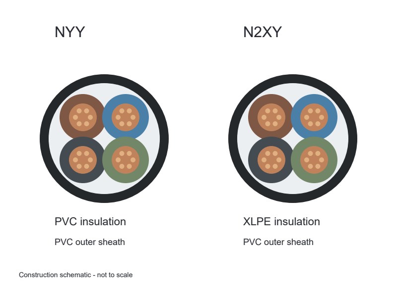
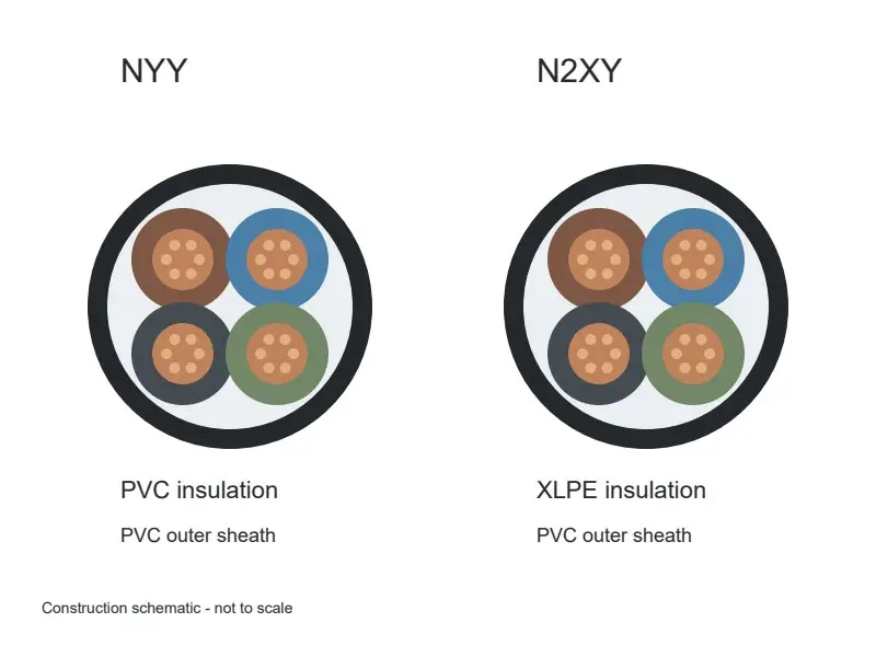
N2XY and NYY are both commonly specified as 0.6/1 kV copper power cables with a PVC outer sheath. The main change is the insulation around each conductor: XLPE in N2XY, PVC in NYY. Typical continuous conductor limits are 90°C and 70°C respectively. That gives N2XY useful thermal headroom, but the installed current rating still depends on the route and the equipment connections. For a fixed feeder, the worthwhile comparison is therefore the complete circuit—not a promise that changing two letters will reduce the conductor size. Both families remain relevant where their construction and installation conditions match the project.
N2XY vs NYY: keep the comparison like for like
Consider two copper cables with the same voltage rating, core arrangement and nominal conductor area. Changing PVC insulation to XLPE changes one important part of that design. It does not automatically change the sheath, add armour or alter which cores serve as phase, neutral and protective earth.
| Detail | N2XY | NYY |
|---|---|---|
| Produktfamilie | N2XY power cable | NYY-J power cable, with a protective conductor |
| Leder | Kobber, with the specified conductor class | Kobber, with the specified conductor class |
| Conductor insulation | XLPE | PVC |
| Ydre kappe | PVC | PVC |
| Common rated voltage U0/U | 0.6/1 kV | 0.6/1 kV |
| Typical maximum continuous conductor temperature | 90°C | 70°C |
| Standard unarmoured construction | Mechanical protection provided by the specified cable and installation | Mechanical protection provided by the specified cable and installation |
These are family-level distinctions, not an interchangeable datasheet. Dirigent klasse, bedding, core identification and dimensions belong to the actual product configuration. The temperature figures describe the conductor in service; they are not ambient-temperature limits or installation-temperature allowances.
The J suffix identifies a green/yellow protective conductor in NYY-J. A core schedule must retain the intended earth and neutral arrangement when a model changes. Four equal-sized cores do not, by themselves, identify the circuit functions.
The thermal advantage has to reach the connection
The useful question is whether the equipment can accept the conductor temperature used in the cable calculation. A cable’s insulation capability and a terminal’s permissible operating condition are separate design inputs.
A practical example comes from IET guidance on BS 7671: equipment connections commonly require a 70°C basis unless suitability for higher conductor temperatures is established. That is a specific installation-code context, not a universal rating for every terminal. An international project follows its applicable rules and equipment documentation.
For N2XY, the implication is straightforward: use the XLPE capability where the assembly supports it. A 90°C catalogue rating alone does not justify loading a connection beyond its permitted condition.

We would settle this interface early in a feeder design. It is more useful than comparing two headline ampere figures and discovering later that the distribution board requires a different operating basis.
Compare the route before comparing the ampere column
For a meaningful current-rating comparison, hold the conductor material and area, number of loaded conductors, laying arrangement and environmental assumptions consistent. A cable in free air and a cable in a buried duct have different heat paths. Gruppering, soil properties and nearby circuits can change the result again.
IEC 60287-1-1 describes a steady-state rating framework based on cable losses, construction and surrounding conditions. The material name is one input to that calculation, not a complete current rating.
Illustrative comparison: a proposed substitution keeps a four-core 95 mm² copper feeder at 0.6/1 kV. To compare NYY and N2XY, the calculation retains the same loaded-core arrangement, route and ambient assumptions, then applies the appropriate conductor-temperature and equipment limits. This is a comparison method, not a published current rating for either cable.
If the XLPE option permits a smaller conductor, voltage drop and fault protection still have to pass. A thermally acceptable smaller cable can have more resistance and a different fault-loop impedance. The cable’s short-circuit withstand also belongs with the protective device’s clearing behaviour.
That is why a fixed percentage uplift—or a promise to go down one conductor size—adds little value without the installation calculation. The useful result is a cable schedule that satisfies the same circuit duty under stated conditions.
The PVC sheath remains part of the decision
N2XY keeps a PVC outer sheath. Its XLPE insulation does not turn the complete cable into a low-smoke, halogen-free construction. Flame propagation, røg, halogen-acid-gas behaviour and circuit integrity answer different questions and use different test methods.
IEC 60332-1-2 addresses flame propagation on a single cable; group installations have a different test scope. IEC 60754-1 addresses halogen acid gas from cable materials. A result from one test cannot stand in for all fire-performance requirements.
Where the project specifically needs a halogen-free sheath system, the decision changes beyond NYY versus N2XY. Our NYY and N2XH comparison explains that separate material choice.
The same principle applies underground: insulation capability and mechanical protection have different jobs. Ducts, backfill, impact exposure, pulling conditions and any required armour shape the installation. Both NYY and N2XY can serve suitable fixed routes under their product specifications; neither model name alone settles every burial condition.
Where each option earns its place in a feeder schedule
| Feeder situation | Reasoned direction | What decides the final design |
|---|---|---|
| A protected fixed feeder comfortably meets its load and voltage-drop requirements on a 70°C basis | NYY remains a practical option; XLPE is not automatically necessary. | Required standard, route suitability and the complete cable quotation. |
| A heavily loaded feeder has equipment suitable for the proposed higher operating temperature | N2XY merits comparison for its XLPE thermal capability. | Installed current rating, leder størrelse, fault duty and termination conditions. |
| Equipment limits keep the connection on a lower-temperature basis | Compare N2XY using that basis rather than its headline 90°C rating. | Permitted equipment temperature and the selected calculation method. |
| The specification changes to a halogen-free route or calls for armour | Develop the required sheath or armour construction as a separate choice. | Fire-performance evidence or mechanical protection, alongside the electrical duty. |
Til XWA, the strongest reason to propose N2XY is a clear benefit in the actual feeder—not a general claim that XLPE is always better. NYY can be entirely appropriate when its rating and route performance meet the requirement. Material selection becomes valuable when it changes a real operating, installation or whole-project cost constraint.
Cost comparison follows the resulting design. Områdekonduktør, kernearrangement, finished diameter, length and accessories all affect the supplied package. A higher-temperature insulation system may create useful design flexibility, but it does not establish a universal saving or price premium.
XWA supplies these fixed power cable families. For a like-for-like quotation, send the proposed cable schedule and route, together with any equipment-temperature constraint that controls the feeder. The discussion can then stay focused on the construction the circuit will actually use.