
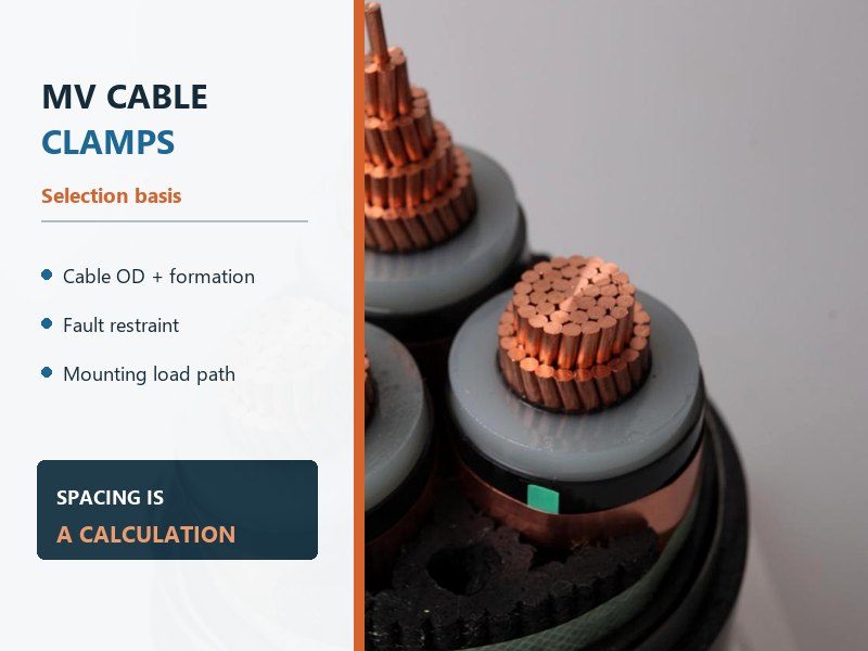
সংক্ষিপ্ত উত্তর: an MV cable clamp should not be selected by cable diameter alone, and its spacing should not come from one generic rule. The final restraint schedule must satisfy cable outside diameter and formation, static weight and sag, peak short-circuit force, axial load on vertical runs, thermal movement, route geometry, পরিবেশগত এক্সপোজার, and the capacity of the rail and supporting structure. For single-core AC circuits, the clamp system must also avoid a closed ferrous path around one phase.
The term cable clamp is common in project schedules and searches. আইইসি 61914 generally uses cable cleat for a device that secures cables to a mounting surface and may provide declared resistance to electromechanical forces. The engineering duty matters more than the label.
A clamp is not automatically a short-circuit restraint
Several products can hold a cable, but they do not prove the same performance. A complete schedule should separate routine support from fault restraint and formation control.
| Component | Normal role | Required project check |
|---|---|---|
| Cable cleat or clamp. | Secures one cable or a cable group to a mounting surface. | Diameter range, formation, axial/lateral retention, electromechanical declaration, উপাদান, এবং পরিবেশ. |
| Intermediate restraint. | Holds cables together in a defined formation between primary cleats. | Declared role, spacing sequence, compatibility with the primary cleat system, and lateral duty. |
| Cable tie. | Manages or groups wiring under its stated mechanical and environmental classification. | It should not be treated as a fault-rated cleat unless the complete application has an appropriate declaration. |
| Cable tray or ladder. | Provides continuous or intermittent route support. | Rail strength, rung loading, bracket spacing, ক্ষয়, বন্ধন, and attachment to the structure. |
| Gland or termination. | Seals, connects, and controls the cable interface at equipment. | It should not carry cable weight or fault movement unless the equipment design explicitly provides that support. |
দ আইইসি 61914:2021 scope page identifies requirements and tests for cleats and intermediate restraints. It also states that cleats provide resistance to electromechanical forces where that performance is declared. This wording is important: a clamp shape or metal body does not prove short-circuit performance.
There is no universal MV cable clamp spacing
Spacing is the result of several independent checks. A value that controls a straight horizontal run may not control a vertical riser, a bend, a termination approach, or a route with higher short-circuit duty.
| Limit state | What creates the demand | What the design must prevent |
|---|---|---|
| Static support. | Cable weight between supports. | Excessive sag, point loading, jacket deformation, and route misalignment. |
| Electromechanical restraint. | Peak current and magnetic interaction during a fault. | Cable displacement, cleat failure, fastener pull-out, impact with adjacent systems, and accessory damage. |
| Axial support. | Cable weight on vertical or steep routes. | Downward slip and transfer of cable weight into a gland, bushing, যৌথ, or termination. |
| Thermal movement. | Expansion and contraction during load cycles. | Uncontrolled walking while avoiding excessive local grip that blocks necessary movement. |
| Local route control. | Bends, offsets, transitions, ক্রসিং, and termination approaches. | Movement that reduces bending radius, changes formation, or loads an accessory. |
| Environmental durability. | Corrosion, fire exposure, তাপমাত্রা, UV, রাসায়নিক, কম্পন, or water. | Loss of mechanical properties before the intended service life. |
The governing spacing is the most restrictive result after all applicable checks. A utility manual may publish a maximum value for its own approved cables and support system. That value remains a network-specific requirement, not evidence that the same distance applies to another cable diameter, দোষ স্তর, cleat, rail, or mounting structure.
Short-circuit restraint starts with the correct electrical data
Normal load current sizes the thermal operating system, but it does not define the highest mechanical force on a cable span. During a short circuit, instantaneous phase currents interact magnetically. The force rises sharply as peak current rises, and it also changes with cable-center spacing, ফেজ বিন্যাস, span length, support geometry, and fault waveform.
A restraint calculation therefore needs more than the symmetrical RMS fault current. The project basis should identify prospective RMS current, peak or asymmetry basis, দোষের সময়কাল, protection clearing sequence, number of fault events required by the specification, cable formation, and center spacing. The selected cleat declaration or test arrangement must then match those conditions closely enough for the responsible engineer to accept the application.
Conductor thermal withstand remains a separate check. আইইসি 60949 addresses thermally permissible short-circuit currents, including non-adiabatic effects. It does not replace the mechanical assessment of the cleat span. A cable can pass the conductor-temperature calculation while its unsupported length, cleat, or mounting rail remains mechanically inadequate.

Short-circuit restraint is a complete load path
The cable pushes or pulls against the cleat. The cleat transfers that demand into bolts or other fasteners. The fasteners load a rail, rung, bracket, or frame. That member finally transfers the event into a wall, floor, steelwork, or foundation. Weakness at any interface breaks the restraint system.
এই কারণে, a cleat’s declared short-circuit performance cannot be applied to an arbitrary support. The test mounting arrangement, fixing-hole geometry, fastener grade and engagement, rail section, bracket orientation, edge distances, substrate anchors, and corrosion condition all affect the installed capacity. Extra washers or an improvised adapter plate can also change the load path.
The support check should include combined effects where relevant. Static cable weight, dynamic fault force, vertical axial load, bracket bending, and torsion may act on the same assembly. Parallel circuits on one ladder can create a different support demand from one isolated circuit.
Formation changes the restraint system
Trefoil formation
Trefoil places three single-core phases in a compact triangular group. A trefoil cleat normally encloses the three phases as one formation. The cleat opening must match the actual cable outside diameter range, including manufacturing tolerance, and the declared test arrangement should represent the same formation.
Intermediate restraints can help preserve trefoil geometry between primary cleats, but they do not automatically replace the primary short-circuit-rated restraints. Their material, spacing sequence, and lateral performance must agree with the cleat system.
Flat formation
Flat formation changes phase-center distances, চৌম্বক আচরণ, তাপীয় রেটিং, support width, and the direction of cable movement during a fault. A cleat tested in trefoil should not be assumed suitable for flat formation. The order and spacing of phases also need to remain consistent along the route, especially where parallel circuits share a support.
Formation is therefore part of both the restraint schedule and the cable rating study. Changing from trefoil to flat during installation is a design change, not a field adjustment.
Single-core AC cables need a non-magnetic restraint path
A closed ferrous loop around one single-core AC cable can experience induced current and local heating. Suitable designs use non-magnetic materials or arrange ferrous support openings so all phase conductors pass through the same magnetic boundary where the governing design permits it.
Material selection also goes beyond magnetism. Stainless steel grade, অ্যালুমিনিয়াম খাদ, polymer or composite properties, plated components, liners, and fasteners need to suit corrosion, তাপমাত্রা, আগুন, UV, কম্পন, and chemical exposure. Mixed metals require attention to galvanic corrosion, especially in wet or coastal routes.
সম্পূর্ণ এমভি পাওয়ার তার route may pass through indoor switchgear rooms, outdoor racks, টানেল, পরিখা, and termination structures. One clamp material or mounting detail may not suit every zone.
Fit must restrain the cable without damaging it
Cable outside diameter is a tolerance range, not one perfect number. The approved cable datasheet should provide the finished diameter basis used to select the cleat. The liner, closing range, bolt position, and installation method must accommodate that range without crushing the sheath or leaving the cable free to move excessively.
An undersized clamp can indent the outer sheath, concentrate pressure over armor or screen layers, and create a point where thermal cycling or vibration damages the cable. An oversized clamp may not control the cable during a fault. Adding unapproved packing material changes friction, compression, আগুন আচরণ, and the tested geometry.
The cable should be inspected at every restraint after installation. Surface marks, ovality, displaced liners, sharp edges, trapped debris, uneven closing gaps, and hardware that bottoms out before gripping the cable are reasons for correction. Tightening follows the approved cleat instructions and project procedure; an invented universal torque is not appropriate.
Vertical routes, bends, and terminations need local decisions
Vertical and steep routes
Vertical runs add axial cable weight to the restraint system. The upper cleats, intermediate supports, rail, and structural anchors must prevent downward movement without imposing damaging local pressure. Long vertical routes may need a dedicated axial-load arrangement rather than the same spacing used on a horizontal ladder.
Bends and route transitions
At a bend, the restraint schedule must preserve the final bending radius and control movement in the direction that matters. Cleats placed too close to a curve can force a local kink; cleats placed too far away can allow the cable to shift under fault or thermal movement. The existing guide to MV cable bending radius and pulling tension explains why the installed radius and pulling geometry require separate checks.
Terminations and equipment entries
A termination bushing or cable gland should not become the cable support by default. A clamp close to the equipment entry can remove cable weight and route movement from the accessory, but it must leave enough straight length and working clearance for the termination design. The location should appear on the cable layout and accessory drawing.
For a 15কেভি তারের circuit, the final support drawing should coordinate cable diameter, screen and sheath construction, termination dimensions, phase formation, নমন ব্যাসার্ধ, বন্ধন বাড়ে, and cleat positions. Treating these as separate site decisions can create incompatible interfaces.
Build a restraint schedule before installation
A useful schedule contains enough information to reproduce the engineering decision rather than only listing a clamp model:
- Cable data: ভোল্টেজ ক্লাস, single-core or multi-core construction, কন্ডাকটরের আকার, cable mass, nominal and tolerance outside diameter, খাপ উপাদান, armor if present, and minimum installed bending radius.
- Arrangement: trefoil, flat, triplex, parallel-circuit order, cable-center spacing, route orientation, and transitions between formations.
- Fault basis: prospective RMS current, peak-current basis, সময়কাল, protection clearing sequence, and required event duty.
- Cleat declaration: cable range, formation, tested arrangement, electromechanical duty, axial and lateral duty where applicable, liner, environmental class, and installation instructions.
- Mounting system: fastener specification, rail or rung section, bracket spacing, structural attachment, জারা সুরক্ষা, বন্ধন, and calculated load capacity.
- Route exceptions: vertical runs, bends, জয়েন্টগুলোতে, সমাপ্তি, ক্রসিং, fire zones, wet areas, রাসায়নিক এক্সপোজার, and vibration.
This schedule also improves factory and site coordination. The approved cable outside diameter can be checked against the cleat range before shipment, while the support contractor can confirm rails, বন্ধনী, and anchors before cable pulling begins.
Installation and inspection sequence
- Verify the approved documents. Confirm the latest cable datasheet, route drawing, restraint schedule, support calculation, and cleat instructions.
- Inspect the support system. Check rail orientation, bracket attachment, জারা সুরক্ষা, edge condition, bonding provisions, and clear access to fasteners.
- Protect the cable during pulling. Keep rollers and pulling geometry separate from permanent restraints; do not close cleats over a moving cable unless the approved method requires it.
- Set formation before final tightening. Maintain phase order, cable-center spacing, trefoil contact, বাঁক ব্যাসার্ধ, and parallel-circuit arrangement.
- Install the declared components. Use the specified liner, fasteners, washers, locking method, and tightening procedure without improvised packing.
- Inspect every local risk point. Give extra attention to vertical sections, bends, transitions, জয়েন্টগুলোতে, সমাপ্তি, and the first supports near equipment.
- Record the completed route. Keep inspection results, photographs, component identification, বিচ্যুতি, and approvals with the commissioning file.
Questions that require project-specific answers
What is the normal spacing for an MV cable clamp?
No universal distance applies. Spacing is calculated from cable weight and sag, দোষ দায়িত্ব, formation, cleat declaration, support capacity, route orientation, thermal movement, and local conditions. A published utility maximum applies only within that utility’s stated system.
Can heavy-duty cable ties replace MV cable cleats?
স্বয়ংক্রিয়ভাবে নয়. Cable ties and cable cleats have different standard scopes and declarations. A tie may manage formation between cleats, but fault restraint requires evidence for the complete installed arrangement.
Is cable diameter enough to select a cleat?
না. Diameter confirms fit. The selection also needs cable formation, শর্ট সার্কিট দায়িত্ব, axial and lateral loads, উপাদান, liner, পরিবেশ, mounting system, and route geometry.
Why are non-magnetic cleats used for single-core AC cable?
They avoid a closed ferrous path around one phase that could develop induced current and local heating. The complete support arrangement still requires mechanical, ক্ষয়, and fault-restraint checks.
Should a clamp be installed directly below a termination?
A nearby support often prevents cable weight and movement from loading the gland or bushing. Its exact position must also preserve the required straight length, নমন ব্যাসার্ধ, termination workspace, ফেজ ব্যবধান, and bonding-lead route.
ইঞ্জিনিয়ারিং উপসংহার
An MV cable clamp is part of the cable system, not a minor hardware item. Outside diameter determines whether the cable fits, but it does not establish fault restraint or spacing. The accepted design must connect electrical fault data, cable formation, static and axial loads, cleat declarations, fasteners, rails, বন্ধনী, গঠন, route geometry, এবং পরিবেশগত এক্সপোজার.
The most reliable rule is simple: calculate spacing for the real cable and real support system, then verify the installed load path. That approach prevents a strong cleat from being paired with a weak rail, an unsuitable fastener, or an unsupported termination.
Send MV Cable and Route Data
For cable and restraint coordination, সিস্টেম ভোল্টেজ প্রদান, তারের নির্মাণ, কন্ডাকটরের আকার, single-core or multi-core arrangement, outside-diameter range, cable mass, trefoil or flat formation, prospective fault data, route orientation, support drawings, পরিবেশগত এক্সপোজার, termination locations, ড্রাম দৈর্ঘ্য, পরিমাণ, এবং গন্তব্য. এক্সডব্লিউএ পাওয়ার & Cable can align the cable datasheet and route interface information with the stated project basis.