
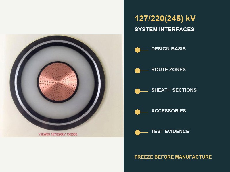
Короткий ответ: лечить 220 Спецификация подземного кабеля кВ как схема системного интерфейса, не как таблица данных кабеля. Перед изготовлением, подключить электропроводку, зоны маршрута, секции оболочки, аксессуары, заводские длины, и свидетельство о приемке. Открытый интерфейс по-прежнему может выдавать неправильную длину., несовместимые аксессуары, несбалансированная схема соединения, или доказательства, которые не относятся к поставляемой системе.
МЭК 62067:2022 является контролирующей международной базой по производству и испытаниям экструдированных одножильных кабельных систем, указанных выше. 150 кВ и до 500 Номинальное напряжение кВ при обычных условиях стационарной установки. Он не дает одного универсального 220 строительство кВ, пропускная способность, расположение ножен, длина барабана, или проектирование маршрута. Эти решения исходят из интерфейсов проекта..

Спецификация должна определять систему, это не маркировка напряжения
«Кабель из сшитого полиэтилена 220 кВ по стандарту IEC 62067» — отправная точка, не полная спецификация. Общее обозначение 127/220(245) кВ регистрирует напряжение относительно земли, номинальное напряжение системы, и максимальное напряжение системы. Там еще ничего не сказано о постоянной нагрузке., обязанность по вине, материал проводника, потери на маршруте, водный барьер, ток повреждения оболочки, метод склеивания, аксессуары, сила установки, или границы доказательств.
МЭК 60183 рассматривает выбор высокого напряжения как скоординированное решение, включающее размер проводника., уровень изоляции, строительство, аксессуары, специальное приклеивание экрана, и условия окружающей среды. МЭК 60287 затем предоставляет уравнения стационарного рейтинга и потерь, намеренно оставляя важные конструкции, среда, и согласованные затраты на прибыль от услуг в реальном проекте. Вот почему каталожная пропускная способность не может закрыть 220 проектирование трассы кВ.
| Интерфейс для заморозки | Минимальные контролируемые входы | Что может выйти из строя, если он останется открытым |
|---|---|---|
| Основа электрического проектирования. | U0/U(Один), частота, заземление, постоянная и циклическая нагрузка, аварийная служба, ток и продолжительность повреждения, импульсный и коммутационный режим. | Неправильная основа изоляции, проводник зоны, металлическая оболочка, или класс аксессуаров. |
| Маршрут и тепловая модель. | Зоны установки, данные о почве/засыпке, каналы, туннельный воздух, глубина, расстояние, формирование, переправы, соседние источники тепла. | Непроверенный номинальный ток или локальное тепловое место. |
| Кабельная конструкция. | Дирижер, система из сшитого полиэтилена, блокировка воды, металлическая оболочка, внешняя оболочка, пожарная или экологическая декларация. | Строительство, не соответствующее маршруту, вина, вода, или условия интерфейса. |
| Система оболочек. | Схема соединения, длины секций, заземление, поля ссылок, склеивание выводов, SVLs, исследование постоянного и переходного напряжения. | Оборотные потери, небезопасное напряжение оболочки, или недостаточная координация изоляции. |
| Аксессуары. | Тип соединения, тип завершения, подключенное оборудование, размеры, материалы, полевое управление, механические и уплотнительные интерфейсы. | Номинально подходящий аксессуар, не входящий в семейство сертифицированных систем.. |
| Длина и логистика. | Цепной маршрут, суставные отсеки, направление вытягивания, пределы барабана, транспортный конверт, план хранения и обработки. | Дополнительные суставы, недоступные бухты, неподходящие барабаны, или невозможно тянет. |
| Доказательства и принятие. | Стандартное издание, конверт для предварительной квалификации и типовых испытаний, плановые/выборочные тесты, ИТП, записи сайта, испытание после укладки. | Отчеты, не охватывающие поставленную конструкцию или установленную схему.. |
Данные маршрута должны вводиться как контролируемые зоны.
Длинный подземный контур редко имеет одну тепловую среду.. Прямое захоронение, воздуховоды в бетонной оболочке, горизонтально-направленное бурение, подходы к мосту, туннели, суставные отсеки, записи подстанции, и перегруженные переходы создают отдельные зоны. Каждая зона нуждается в цепочке, геометрия, тепловые предположения, метод установки, и статус проекта. Управляющий рейтинг может исходить из короткого ограничительного сегмента, а не из среднего маршрута..
Отдельное руководство XWA по ограничения подземного маршрута объясняет термический, тянет, и гражданские последствия в деталях. Для 220 спецификация кВ, суммировать эти вычисления в регистре интерфейса маршрута. Запись границ зоны, утвержденные ресурсы, ответственная дисциплина, пересмотр расчета, и любая чувствительность, которая все еще влияет на выбор проводника или конструкции..
Три значения заслуживают явных исходных записей.: тепловое сопротивление грунта или засыпки, температура окружающей среды или почвы, и расположение кабелей. Родовое значение, скопированное из таблицы тендеров, не эквивалентно маршрутному свидетельству.. Где сушить, сезонное изменение, или неопределенная занятость воздуховода является достоверной, рейтинговое исследование должно объяснить лечение. Не прячьте эту неопределенность внутри одного значения токовой нагрузки..
Конструкция оболочки создает собственную схему секций.
В 220 кВ, металлическая оболочка является частью электрической и тепловой системы. Он обеспечивает скрининг, несет указанную ответственность за неисправность, и взаимодействует с водозащитой и аксессуарами. Расположение соединения влияет на постоянное напряжение оболочки., циркулирующий ток, потери, текущий рейтинг, защита от перенапряжения, и безопасные условия труда.
Одноточечное соединение, прочное соединение, и перекрестная связь являются инженерными вариантами, не качественные оценки. СИГРЭ ТБ 797 подчеркивает, что системы передачи переменного тока уровня и выше 66 кВ требуют индивидуальной конструкции соединения оболочек на основе кабеля, аксессуары, условия установки, и подключенная система. Перекрестная связь распространена на более длинных 220 кВ, поскольку сбалансированные второстепенные секции могут снизить чистое наведенное напряжение и потери на циркуляцию., но это не автоматическое правило.
| Решение о склеивании | Данные, которые необходимо согласовать | Обязательная запись |
|---|---|---|
| Длина основных и второстепенных секций. | Цепной маршрут, фазовое расположение, позиции совместных отсеков, геометрия кабеля. | График секций с фактической и расчетной длиной. |
| Соединительные коробки и соединительные выводы. | Расположение, доступность, обязанность кондуктора, уровень изоляции, заземление. | График оборудования и схема вывода. |
| Ограничители напряжения оболочки. | Постоянное напряжение промышленной частоты, переходное исследование, энергетический долг, координация изоляции. | Допущения исследования и выбранная рейтинговая основа. |
| Размер металлической оболочки. | Ток повреждения, продолжительность, обратные пути, режим соединения, пределы материала и температуры. | Расчет аварийной нагрузки связан со строительным чертежом. |
| Ввод в эксплуатацию контрольных точек. | Изоляция раздела, ссылки, земли, доступ к внешней оболочке, интерфейсы мониторинга. | Тестовая схема, соответствующая заводским соединениям. |
Таким образом, поздний переход на соединительный пролет меняет не только гражданскую цепочку.. Это может нарушить баланс малых секций., длина поставки кабеля, расположение окна ссылок, длина соединительного провода, вытягивание секций, и план испытаний. Верните изменение через регистр интерфейса, прежде чем прекратить производство барабана..
Производственные длины являются результатом инженерной мысли.
Определите длину поставки на завод на основе анализа цепочки маршрутов и монтажа., не только от максимальной емкости барабана. Полезный график длины выравнивает четыре слоя: доступные позиции совместных отсеков, возможные тяги, сбалансированные секции склеивания, и переносные барабаны. Сюда также входят выходные пособия, надбавки к совместной подготовке, допуски маршрута, образец требований, и утвержденная политика в отношении запасной длины.
Ненужные соединения добавляют дополнительные интерфейсы и монтажные работы.. Слишком длинные секции могут превысить массу барабана., транспортный конверт, напряжение, давление на боковую стенку, или возможность обработки сайта. Таким образом, оптимальный график – это не «наименьшее количество суставов» изолированно.. Это устройство с наименьшим риском, удовлетворяющее электрическим требованиям., гражданский, установка, логистика, и ограничения по техническому обслуживанию вместе.
В производственном разрешении должна быть указана каждая фаза и барабан., начало и конец цепочки, направление вытягивания, место назначения совместное или прекращение, расчетная длина секции, заказанная длина, размеры и масса барабана, и соответствующая секция склеивания. Маркировка барабанов и упаковочная документация должны использовать те же идентификаторы, что и чертежи и записи на объекте..
Аксессуары должны принадлежать к предлагаемому семейству систем.
Не принимайте 220 Соединение или оконечное соединение кВ только потому, что напряжение, указанное на паспортной табличке, соответствует напряжению кабеля.. Диаметр изоляции кабеля, геометрия экрана, соединение проводника, интерфейсы материалов, и электрическое поле контролирует всю материю. Тепловое расширение, уплотнение, механические нагрузки, и подключенное оборудование также влияют на интерфейс.
СИГРЭ ТБ 968 описывает интерфейсы кабельных принадлежностей как критически важные электрические, термический, материал, и термомеханические границы. Подготовка поверхности, давление на границе раздела, смазка, контроль загрязнения, Совместимость материалов может повлиять на производительность. Поэтому в паспорте аксессуаров должны быть указаны точная конструкция кабеля и диапазон допусков размеров., не универсальный 220 семейная маркировка кВ.
Терминационные интерфейсы также нуждаются в основе подключенного оборудования.: прекращение подачи наружного воздуха, ГИС-интерфейс, или подключение трансформатора; Загрязнение и горные условия; механическая загрузка; фазовый интервал; соглашение о поддержке; граница жидкости или газа, где это применимо; и терминальное оборудование. Соединительным отсекам необходимо рабочее пространство, экологический контроль, заземление, поддерживать, и контролируемая процедура установки.
Карта МВЦ 62067 доказательства предоставленного дизайна
МЭК 62067:2022 определяет требования и тесты для кабельной системы, кабели, и аксессуары в его объеме. Рассмотрите каждый уровень доказательств по назначению. В отчете о предварительной квалификации рассматриваются долгосрочные термоэлектрические характеристики определенного семейства систем.. Данные типовых испытаний относятся к определенной конструкции. Плановые и выборочные испытания касаются выпускаемой продукции.. Записи на объекте и тесты после установки относятся к собранной схеме.. Один документ не может заменить все остальные слои..
| Уровень доказательств | Ответ на вопрос | Проверка интерфейса |
|---|---|---|
| Предварительная квалификация. | Прошло ли семейство систем необходимую долгосрочную квалификацию?? | Сравнить проводник, система изоляции, аксессуары, размеры, материалы, класс напряжения, и разрешенные расширения. |
| Типовые испытания. | Прошла ли заданная конструкция кабеля и аксессуаров применимые проектные испытания?? | Убедитесь, что представлены предложенные комбинации соединений и концевых заделок.. |
| Плановые испытания. | Прошла ли производственная проверка каждая требуемая длина или аксессуар?? | Трассировка отчетов на барабан, фаза, серийный номер аксессуара, и доработка чертежа. |
| Примеры тестов. | Соответствуют ли выбранные производственные характеристики заданным требованиям?? | Определить частоту дискретизации, свидетельские показания, принятие, и обработка несоответствий. |
| Записи об установке. | Был транспорт, тянет, подготовка, расшивка, и прекращение работ под контролем? | Связать персонал, среда, измерения, материалы, фотографии, и контрольные листы. |
| Тесты после установки. | Соответствует ли собранная схема утвержденным условиям ввода в эксплуатацию?? | Возможности источника соответствия, длина маршрута, аксессуары, тестовые соединения, метод, и критерии приемки. |
СИГРЭ ТБ 841 рассматриваются современные источники испытаний после прокладки и их ограничения для систем высокого и сверхвысокого напряжения.. Согласуйте метод, Напряжение, продолжительность, частота источника, диагностические дополнения, и тестовые соединения в графике тестирования проекта. Не импровизируйте после сборки схемы..
Семь точек удержания предотвращают дорогостоящие поздние изменения
- Проектное удержание: заморозить U0/U(Один), заземление, варианты нагрузки, обязанность по вине, координация изоляции, и руководящие издания.
- Удержание модели маршрута: утвердить цепочку, входы зоны, рейтинговая модель, расчеты установки, и неразрешенная чувствительность.
- Удержание системного проектирования: утвердить конструкцию кабеля, дирижер, размеры, металлическая оболочка, водный барьер, и экологические декларации.
- Удержание интерфейса аксессуара: утверждать суставы, прекращение, объемные конверты, подключенное оборудование, и картирование квалификаций.
- Склеивание: утвердить расписание разделов, поля ссылок, заземление, SVLs, координация изоляции, и тестовый доступ.
- Удержание по длине и барабану: утвердить сроки поставки, направление вытягивания, суставные отсеки, детали барабана, допуски маршрута, и идентификаторы.
- План качества сохраняется: утвердить ИТП, шаблоны отчетов, прослеживаемость, свидетельские показания, процесс несоответствия, и метод ввода в эксплуатацию.
В этих точках хранения должны использоваться контролируемые версии и имена владельцев.. СИГРЭ 2026 Работа по обеспечению/контролю качества жизненного цикла определяет управление интерфейсами как центральный риск, поскольку недостатки на ранних этапах проекта могут распространиться на производство., транспорт, установка, и эксплуатация. Таким образом, подписанное техническое описание без закрытых интерфейсов не является надежным производственным релизом..
Практичный 220 Регистр интерфейса кВ
Регистр может оставаться компактным, если в каждой строке будет пять полей.: требование, проверенный ввод, ссылка на доказательства, ответственный владелец, и статус. В открытых позициях должна быть указана дата принятия решения и последующие документы, которые они блокируют.. Самый полезный регистр – не самый длинный; это тот, который делает зависимости видимыми.
- Напряжение и система: 127/220(245) обозначение кВ, Частота переменного тока, заземление, базис перенапряжения, случаи нагрузки и неисправности.
- Маршрут: цепочка, чертежи зон, тепловые значения, формирование, расстояние, глубина, гражданский метод, проверки на растяжение и изгиб.
- Строительство: дирижер, система изоляции, металлическая оболочка, защита воды, внешняя оболочка, размеры и допуски.
- Аксессуары: точные конструкции соединений и заделок, кабельные габаритные окна, подключенное оборудование, условия установки.
- Склеивание: основные/второстепенные разделы, поля ссылок, ведет, земли, SVLs, расчет напряжения оболочки и режима повреждения.
- Производство: расписание фаз/барабанов, заказанная длина, образцы, маркировка, контрольные точки, ограничения на транспортировку и хранение.
- Доказательство: квалификационная матрица, производственные отчеты, досье по отслеживаемости, записи об установке, исполнительный, отчет о вводе в эксплуатацию.
Общие вопросы о 220 характеристики кВ под землей
МЭК 62067 определить текущий рейтинг 220 кВ кабель?
Нет. МЭК 62067 определяет тесты и требования в пределах своей области. Текущий рейтинг зависит от фактического строительства, потери, геометрия установки, тепловая среда, договоренность о склеивании, и эксплуатационная обязанность. МЭК 60287 предоставляет методы расчета, ни одного универсального каталожного значения.
Является ли перекрестное соединение обязательным для каждого 220 кВ трасса?
Нет. Инженеры должны спроектировать систему оболочек для цепи.. Перекрестное соединение часто подходит для более длинных маршрутов.. Одноточечные или сплошные конструкции могут соответствовать определенной длине секции и условиям.. Для решения требуется наведенное напряжение, потеря, вина, преходящий, заземление, и анализ технического обслуживания.
Могут ли позиции соединений ячеек оставаться открытыми до окончания изготовления кабеля??
Это создает большой риск. Соединительные отсеки контролируют длину доставки, вытягивание секций, Баланс соединительной секции, расположение блоков ссылок, количество аксессуаров, и доступ к сайту. Предварительные положения должны блокировать окончательный выпуск барабана, если не существует утвержденного допуска и метода замены..
Подтверждает ли отчет о предварительной квалификации поставку цепи??
Он поддерживает определенное квалифицированное семейство систем.. Сопоставьте предлагаемую конструкцию и аксессуары с этим семейством и правилами его расширения.. Производство, установка, и доказательства ввода в эксплуатацию остаются необходимыми отдельно.
Что входит в окончательную техническую заявку?
Представление должно соответствовать графику кабельного телевидения., строительные чертежи, дополнительные интерфейсы, исследование связей, рейтинговый отчет, график продолжительности поставок, квалификационная матрица, ИТП, производственные отчеты, записи об установке, исполнительные чертежи, и отчет об испытаниях после установки под одним индексом с контролем версий.
Инженерное заключение
Надежный 220 Спецификация подземного кабеля кВ является документом управления интерфейсом.. МЭК 62067 устанавливает основу для тестирования системы. Эффективность проекта также зависит от связей между электрическими, зоны маршрута, строительство, металлическая оболочка, аксессуары, длины, установка, и доказательства. Запускайте производство только тогда, когда каждый барабан и аксессуар имеют прослеживаемый путь от входных данных проекта до позиции маршрута.. По тому же пути следует соединить квалификационный конверт с записью о вводе в эксплуатацию..
Соответствующее XWA 127/220(245) ассортимент продукции кВ предоставляет класс напряжения и контекст конструкции, в то время как более широкий портфолио высоковольтных кабелей помещает его в 66-500 системный диапазон кВ. Для нейтрального инженерного руководства по проектированию оболочки для конкретного проекта., увидеть Технический обзор СИГРЭ.
Отправьте 220 График сопряжения кВ
Для инженерной экспертизы, предоставить U0/U(Один), частота и заземление, постоянные и аварийные нагрузки, ток и продолжительность повреждения, цепочка маршрутов и термические зоны, формирование и гражданский метод, концепция склеивания, интерфейсы объединенных отсеков и терминаторов, необходимая версия МЭК, требования к квалификации и испытаниям, объемы поставки, и пункт назначения. XWA Мощность & Трос позволяет выровнять предлагаемую конструкцию, данные интерфейса аксессуара, производственная длина, и график доказательств на основе утвержденной системы. Окончательное подтверждение возможностей следует за закрытием технических интерфейсов..